Volkswagen Passat B6 represents the 6th generation of the Passat model range. It was produced in 2005, 2006, 2007, 2008, 2009 and 2010 with both gasoline and diesel engines with sedan and station wagon bodies. The 4-door coupe based on the Passat B6 represents a separate model and is called the Passat CC and was produced from 2008 to 2015. In this article we will provide a description of the fuse and relay blocks of the Volkswagen Passat B6 (CC) with diagrams and photos. We will separately highlight the fuse responsible for the cigarette lighter.
Please note that the number of blocks and their execution options may differ from this material and depend on the year of manufacture and the level of electrical equipment of your car.
General arrangement of blocks Volkswagen Passat B6 CC
Scheme
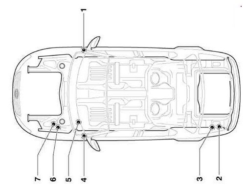
- Fuse block on the passenger side instrument panel
- Block next to the battery
- Block behind the trim in the luggage compartment
- Fuse block on the driver’s side instrument panel
- Relay blocks
- Fuse and relay box under the hood
- Main fuse block
Blocks in the cabin Volkswagen Passat B6 CC
Driver’s side fuse box
It is located on the left side of the instrument panel behind a protective cover.
Photo – example
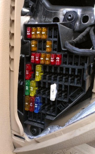
Scheme
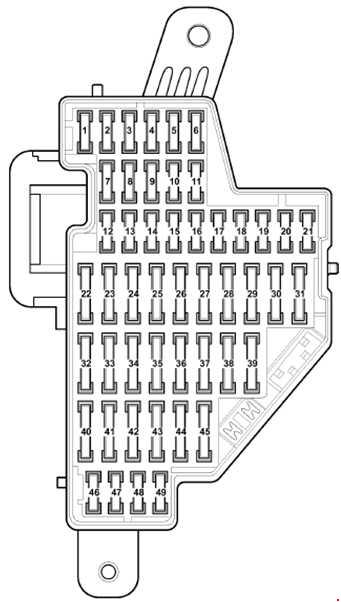
Description Option 1.
It was used mainly until April 2008.
| 1 | 10A Diagnostic Connector |
| 2 | 5A ASR and ESP off button, AUTO HOLD button |
| 3 | 5A Power steering control unit |
| 4 | 5A Brake light switch |
| 5 | 10A Headlight leveling regulator, Headlight leveling actuator, Left headlight control unit |
| 6 | 5A Trailer recognition control unit |
| 7 | 5A Instrument cluster control unit, Diagnostic data bus interface |
| 8 | 5A Rear window blind switch (until May 2005), Garage door opener control panel (until May 2005), Rear window blind control unit (until May 2005), Electrochromic interior rear-view mirror |
| 9 | 10A All-wheel drive system control unit |
| 10 | 5A Motronic power relay, Engine control unit |
| 11 | 5A Emergency data recorder key, Taximeter mirror, Tachograph |
| 12 | 10A Driver’s door control unit, Right rear door control unit (from May 2006) |
| 13 | 10A Light switch, diagnostic connector |
| 14 | 5A Electronic steering column lock control unit |
| 15 | 5A On-board network control unit, Front interior lighting lamp |
| 16 | 10A Electronic ignition lock |
| 17 | 10A Receiving module 1 of the interior security system or additional heater, Rain and light sensor, Vehicle tilt sensor, Alarm siren |
| 18 | Not used |
| 19 | Not used |
| 20 | Not used |
| 21 | Not used |
| 22 | 10A Air flow meter 5A Electric fuel pump relay 2 |
| 23 | 10A Crankcase ventilation system heating resistor (version for countries with cold climates) |
| 24 | 5/20A Reverse light switch, multifunction switch, automatic transmission control unit, DSG gearbox Mechatronic unit |
| 25 | 10A Injectors (until November 2005), 10A Garage door opener control panel (until April 2006) |
| 26 | 10A Rear window blind switch (from May 2005), Rear window blind control unit (from May 2005) |
| 27 | 5A Supply fan relay, Climatronic control unit |
| 28 | 20A Trailer recognition system control unit (from May 2006) |
| 29 | 20A Trailer recognition control unit (rear left side light, brake light, right/left turn signal) (until April 2006), Electromechanical parking brake control unit (from May 2006) |
| 30 | 15A Trailer recognition control unit, Electromechanical parking brake control unit (from May 2006) |
| 31 | 15/25A Trailer recognition system control unit (until April 2006), (from May 2006) Fuel pump control unit and its relay |
| 32 | 30A On-board network control unit (rear window heating) |
| 33 | 20A Sliding sunroof control unit |
| 34 | 15A Fuel priming pump |
| 35 | 25/30A Headlight cleaning system relay, headlight washer pump |
| 36 | 20A Relay for operation in auxiliary heater mode (except vehicles with Climatronic) |
| 37 | 25A Front seat heating control unit |
| 38 | 15A Trailer recognition system control unit (from May 2006), Cigarette lighter (until April 2006), Rear cigarette lighter – (until April 2006) |
| 39 | 5/40A Supply fan control unit (Climatronic), Air conditioning control unit |
| 40 | 5A Light switch |
| 41 | 15A Cigarette lighter (from May 2006), Rear cigarette lighter (from May 2006), 40A Supply air fan and its relay (until April 2006), |
| 42 | 15A Windshield and rear window washer pump and motor |
| 43 | 20A Auxiliary heater control unit |
| 44 | 20A Relay for operation in autonomous heater mode |
| 45 | 25A 12V Socket |
| 46 | 5A Switches, Engine start button |
| 47 | 15A Taximeter, additional equipment connection points, interior lighting control lamp |
| 48 | 20A Charger connection point (only police vehicles from May 2005) |
| 49 | Not used |
Depending on the year of manufacture, fuse 38 or 41 at 15A is responsible for the cigarette lighter.
Description Option 2.
Cars produced since May 2008.
| 1 | 10A Rear window blinds |
| 2 | 5A ASR and ESP off button, AUTO HOLD button, ABS unit, Electromechanical parking brake control unit |
| 3 | 5A Light switch, Brake light switch, Engine oil level and temperature sensor, Power steering control unit |
| 4 | 5A Electronic damping control system control unit, Trailer recognition control unit, Adaptive lighting and headlight range control unit, Diagnostic connector |
| 5 | 10A Switch and instrument cluster backlight brightness control, Headlight range control, Left headlight control unit |
| 6 | 10A All-wheel drive system control unit |
| 7 | 5A Instrument cluster control unit, Diagnostic data bus interface |
| 8 | 10A Right headlight control unit, Right headlight leveling actuator motor |
| 9 | 10A Airbag control unit, Seat occupancy detection system control unit, Front passenger airbag deactivation indicator lamp |
| 10 | 10A Tiptronic switch, Air flow meter, Fuel pump control unit, Fuel pump control unit, Motronic power relay, Engine control unit |
| 11 | 5A Emergency data recorder key, Taximeter mirror, Tachograph |
| 12 | 10A Driver’s door control unit, Front passenger’s door control unit |
| 13 | 10A Light switch, diagnostic connector |
| 14 | 10A Alarm siren |
| 15 | 5A On-board network control unit, Front interior lighting lamp |
| 16 | 10A Electronic ignition lock, Electronic steering column lock control unit |
| 17 | 5A Electromechanical parking brake button, ABS unit |
| 18 | 10A Crankcase ventilation system heating resistor (version for countries with cold climates) |
| 19 | 7.5A Adaptive cruise control control unit, Parking assistant control unit, Lane keeping assistant control unit, Parking autopilot control unit |
| 20 | 5A Garage door opener control panel |
| 21 | 10A Interior electrochromic rearview mirror, Switch with seat heating control, High pressure sensor, Air pollution sensor, Supply fan relay, Washer jet heating resistor, Climate control unit, Control relay |
| 22 | 20A Electromechanical parking brake control unit |
| 23 | 15A Trailer recognition control unit |
| 24 | 20A Electromechanical parking brake control unit |
| 25 | 20A Trailer recognition control unit |
| 26 | 15A Electronic damping control system control unit |
| 27 | 15/20A Fuel pump relay |
| 28 | 10A Rear door control unit, Central comfort control unit |
| 29 | 25A Rear seat heating control unit |
| 30 | 20A Sliding sunroof control unit |
| 31 | 30A Inverter with socket, 12 – 230 V |
| 32 | 30A On-board network control unit (rear window heating) |
| 33 | 30A Headlight cleaning system relay, Headlight washer pump |
| 34 | 25A Front seat heating control unit |
| 35 | 30A Rear door control unit |
| 36 | 15A Seat lumbar support adjustment switch, Seat cushion angle adjustment button, Seat backrest position adjustment button |
| 37 | 10A Magnetic field sensor for compass, Rain and light sensor, Vehicle tilt sensor, Rear view camera control unit, Climatronic control unit, Additional liquid heater radio signal receiver, Voltage monitoring relay |
| 38 | 40A Supply fan relay, Supply fan control unit, Climatronic |
| 39 | 15A Multifunction switch (only for vehicles with 6-speed automatic transmission), Automatic transmission control unit, Reversing light switch, DSG gearbox Mechatronic unit |
| 40 | 15A Second battery charging relay, Windshield washer pump, Rear window wiper motor |
| 41 | 20A Cigarette lighter |
| 42 | 15A 12 V socket |
| 43 | 20A Auxiliary heater control unit (only if there is a second battery) |
| 44 | 30A Driver and passenger door control unit |
| 45 | 20A Relay for operation in autonomous heater mode (only if there is a second battery) |
| 46 | Not used |
| 47 | 10A Telephone receiver (only vehicles with Start-Stop system) |
| 48 | 5A Control unit in the instrument cluster (only vehicles with Start-Stop system) |
| 49 | Not used |
In this version, fuse number 41 at 20A is responsible for the cigarette lighter. And for additional sockets – 42 at 15A.
Passenger side fuse box Volkswagen Passat B6 CC
Located on the right end of the instrument panel, just like the left one, it is covered by a protective cover.
First version
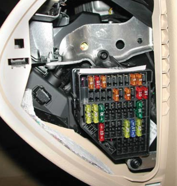
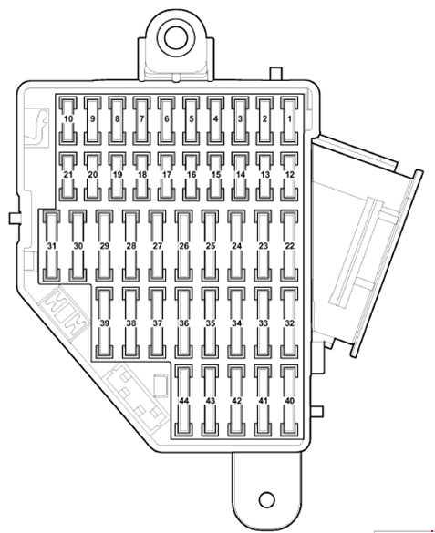
Purpose of fuses
| 1 | 5A Magnetic field sensor for compass (only vehicles from May 2005) |
| 2 | 5A Electromechanical parking brake control unit, ABS control unit |
| 3 | 5A Magnetic field sensor for compass (only vehicles before April 2006), Parking assistant control unit |
| 4 | 5A Adaptive cruise control control unit |
| 5 | 10A Right headlight control unit (only for headlights with gas discharge lamps) |
| 6 | 5A Tiptronic switch |
| 7 | 5A Adaptive lighting and headlight range control unit (only for headlights with gas discharge lamps) |
| 8 | 5A High pressure sensor, Engine oil level and temperature sensor |
| 9 | 10A Front passenger airbag deactivation indicator lamp, Airbag control unit, Seat occupancy detection system control unit |
| 10 | 5A Fuel pump control unit |
| 11 | Not used |
| 12 | 10A Front passenger door control unit, Right rear door control unit (only vehicles before April 2006) |
| 13 | 10A Parking assistant control unit (only vehicles before April 2006) |
| 14 | 5A Rear view camera control unit (only vehicles from November 2007) |
| 15 | 5A Climatronic control unit, Air conditioning control unit |
| 16 | 5A Tiptronic switch |
| 17 | 5A Electromechanical parking brake warning lamp, ABS control unit |
| 18 | Not used |
| 19 | Not used |
| 20 | Not used |
| 21 | Not used |
| 22 | 30A Inverter with socket, 12 – 230 V |
| 23 | 30A Rear door control unit |
| 24 | 30A Rear left door closer control unit (Variant) |
| 25 | 30A Rear right door closer control unit (Variant) |
| 26 | Not used |
| 27 | 25A Rear seat heating control unit |
| 28 | 15A Fuel pump control unit (only vehicles before April 2006) |
| 29 | 30A Driver and passenger door control unit |
| 30 | 20A Electromechanical parking brake control unit (only vehicles before April 2006), Central comfort system control unit (only vehicles from May 2006 to October 2006) |
| 31 | 20A Electromechanical parking brake control unit (only vehicles before April 2006) 15A Fuel pump control unit |
| 32 | Not used |
| 33 | 20A 12 V socket (only vehicles before April 2006) |
| 34 | 15A Fuel pump control unit |
| 35 | 20A Cigarette lighter (only vehicles before April 2006) |
| 36 | Not used |
| 37 | Not used |
| 38 | 15A 12 V socket (only vehicles from May 2006) |
| 39 | 10A Seat heating regulator, Climatronic control unit, Second battery charging relay, Washer jet heating element |
| 40 | 5A Emergency data recorder (only taxi vehicles before May 2005) |
| 41 | 15A Taximeter, Mirror with taximeter, Button illumination lamp when alarm is activated, Connection point in glove box and luggage compartment |
| 42 | 20A Connection point in the glove box (only vehicles in taxi version before May 2005) |
| 43 | 5A Taxi anti-theft alarm remote control unit, Connection point in glove box and luggage compartment |
| 44 | 10A Taxi Anti-Theft Alarm Remote Control Unit, 12V Socket |
Fuse number 35 at 20A is responsible for the cigarette lighter.
Second version
Used on cars from May 2008 onwards
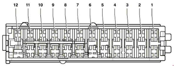
Decoding the scheme
| 1 | 30A Control unit 2 luggage compartment lids (Variant only) |
| 2 | 30A Trunk lid control unit (Variant only) |
| 3 | Not used |
| 4 | Not used |
| 5 | Reserved for special vehicles |
| 6 | Reserved for special vehicles |
| 7 | Reserved for special vehicles |
| 8 | Reserved for special vehicles |
| 9 | Reserved for special vehicles |
| 10 | Not used |
| 11 | Not used |
| 12 | Not used |
Relay blocks
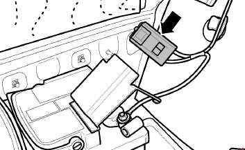
They are located under the dashboard on the driver’s side. The on-board network control unit is also located there.
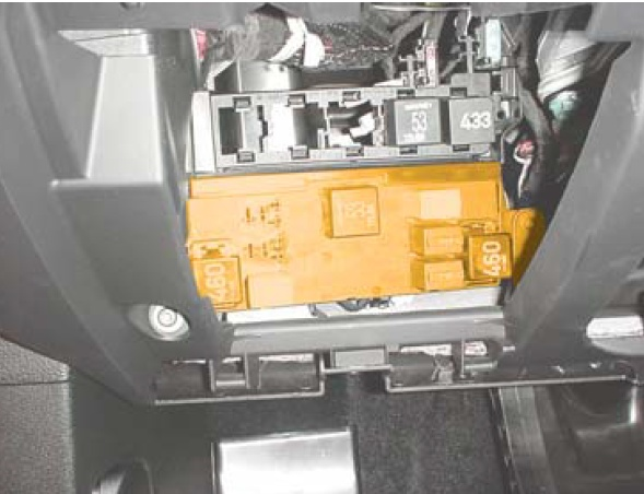
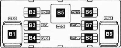
Element designation
| B 1 | Terminal 15 voltage supply relay (460) |
| B 2 | Free |
| B 3 | Free |
| B 4 | Terminal 30 voltage supply relay (449) |
| B 5 | Rear window heating relay, (53) |
| O 6 | Double horn relay, (449) |
| Ot 7 | Dual Washer Pump Relay #1 (404) |
| B 8 | Dual Washer Pump Relay #1 (404) |
| O 9 | Relay terminals X, (460) |
An additional relay holder is attached to the on-board network control unit. In vehicles with seat heating, this unit contains thermal bimetallic fuses for the heating elements.
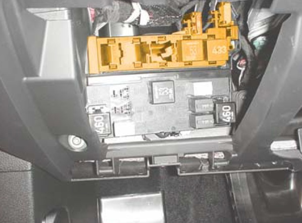
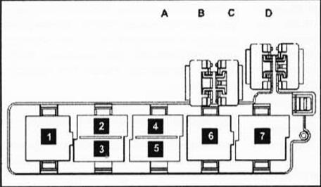
Description
- Auxiliary heater relay, (53)
- Free
- Fresh air fan relay, (404)
- Free
- Fuel pump relay #2, (404)
- Headlight washer relay, (53)
- Terminal 50 (433) voltage supply relay
- A – Reserve
- B – Reserve
- C – Thermal fuse No. 1 (30 A) driver’s seat position adjustment
- D – Thermal fuse No. 2 (30 A) driver’s seat position adjustment
Blocks under the hood Volkswagen Passat B6 CC
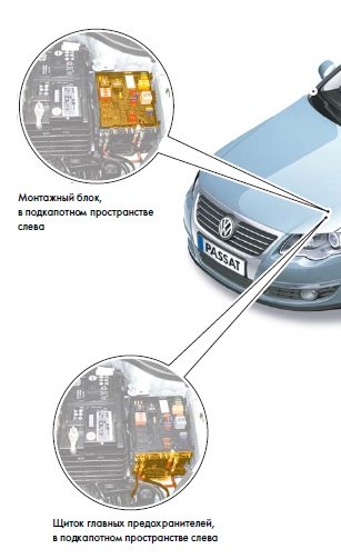
The fuse and relay block is located in the left part of the engine compartment and consists of 2 sections: a mounting block and a section for high-power main fuses.
Mounting block
Option 1
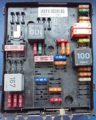

Fuse designations
| 1 | 5/15A Automatic transmission control unit, DSG gearbox Mechatronic unit |
| 2 | 30A ABS control unit |
| 3 | 20A Central control unit for the comfort system (until April 2006), Trailer recognition system control unit (from May 2006) |
| 4 | 5A On-board network control unit |
| 5 | 20A Audible signal |
| 6 | 20A Ignition coils with output stages |
| 7 | 15A Fuel pressure regulator, 5A Clutch pedal position sensor |
| 8 | 10A Radiator fan control unit, Gas distribution valve, Ejector pump valve, Intake manifold flap valve |
| 9 | 5A Circulation pump relay |
| 10 | 10A Power relay 2 Motronic, lambda probe heating element |
| 11 | 25/30A Engine control unit |
| 12 | Not used |
| 13 | Not used |
| 14 | Not used |
| 15 | 10A Circulation pump |
| 16 | 5A Steering column control unit |
| 17 | 5A Instrument cluster control unit |
| 18 | 30A Amplifier, Control unit for special vehicles |
| 19 | 15/20A Main unit Control unit with radio navigation system display |
| 20 | 20A Mobile phone, TV, digital satellite |
| 21 | 10A TV tuner, Digital satellite radio tuner |
| 22 | 7.5A Multimedia system control unit |
| 23 | 10A Radiator fan control unit, 5A Magnetic field sensor for compass |
| 24 | 5/10A Data bus diagnostic interface |
| 25 | Not used |
| 26 | 10A Engine control unit, Motronic power relay |
| 27 | Not used |
| 28 | Not used |
| 29 | Not used |
| 30 | 20A Auxiliary heater control unit |
| 31 | 30A Wiper motor control unit |
| 32 | 10A Boost pressure valve |
| 33 | 15A Fuel pressure regulator, Lambda sensor heating element |
| 34 | Not used |
| 35 | 20A Relay for operation in autonomous heater mode |
| 36 | Not used |
| 37 | Not used |
| 38 | Not used |
| 39 | Not used |
| 40 | Not used |
| 41 | Not used |
| 42 | Not used |
| 43 | Not used |
| 44 | 10A Fuel System Diagnostic Pump |
| 45 | 10A Lambda probe |
| 46 | 10A Lambda probe heating element 1 after the catalyst |
| 47 | 40A On-board network control unit, Dipped beam headlights, Side lights |
| 48 | 40A On-board network control unit, Dipped beam headlights, Side lights |
| 49 | Onboard power supply control unit -J519- (terminal 15 supply) |
| 50 | 60A Second battery charging relay |
| 51 | Not used |
| 52 | 60A Windshield heating element |
| 53 | 50A Onboard electrical system control unit, Left fuse box |
| 54 | 50A E/additional air motor, Glow plug relay |
Relay
A1 – Terminal 30 voltage supply relay. , A2 – A4 – reserve
Option 2
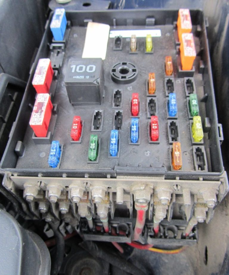
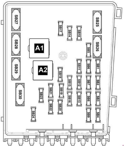
Appointment
| 1 | 7.5A Multimedia system control unit |
| 2 | 30A ABS control unit |
| 3 | 20A Sound signal, On-board network control unit |
| 4 | 20A Central control unit for the comfort system (until April 2006), 25A Control unit for the trailer recognition system (from May 2006) |
| 5 | 5A Battery control unit, On-board network control unit |
| 6 | 5A Automatic Transmission Control Unit, 15A DSG Mechatronic Unit |
| 7 | 15A Control unit with display for TV and radio navigation system, Main unit, Control unit with display for radio navigation system, 30A Voltage stabilizer |
| 8 | 30A Mechatronic Unit DSG |
| 9 | 5A Steering column control unit |
| 10 | 20A Fuel pump relay (diesel engines only), Glow plug control unit, Ignition coils with output stage (cylinders 1 – 4) |
| 11 | 5A Control unit in the instrument cluster (only vehicles with Start-Stop system) |
| 12 | 5A Control unit for electronics controlling a mobile phone, antenna, TV tuner, digital satellite. |
| 13 | 10A Motronic power relay, Power relay cl. 30, Engine control unit |
| 14 | 25/30A Engine control unit |
| 15 | 5/10A Data bus diagnostic interface |
| 16 | 5A Secondary air pump relay, 10A Exhaust gas recirculation valve, Boost pressure limit solenoid valve, Lambda probe heating element |
| 17 | 10A Fuel tank shut-off valve, 40A Low power heater relay (from November 2006) |
| 18 | 5A Heating relay, 10A Coolant pump after engine shutdown, 30A Reductant heating system control unit |
| 19 | 30A Amplifier |
| 20 | 5A Auxiliary fuel pump relay, Radiator fan control unit, Glow plug control unit, 10A Clutch pedal position sensor, Valve 1 of the variable valve timing system, 15A Fuel pressure regulator |
| 21 | 20A Auxiliary heater control unit |
| 22 | 30A Wiper motor control unit |
| 23 | 5A Magnetic field sensor for compass, Glow plug control unit, 10A Electronically controlled engine cooling system thermostat, Radiator fan control unit, Air damper / intake flap motor, Lambda probe heating element, Gas distribution and manifold valve |
| 24 | 10/15A Nitrogen oxide emission sensor control unit, Lambda probe heating element |
| 25 | 40A On-board network control unit, Dipped beam, High beam, Dimensions |
| 26 | 40A On-board network control unit, Dipped beam, High beam, Dimensions |
| 27 | 60A Windshield heating element |
| 28 | 40/50A Secondary air pump motor, Glow plug control unit |
| 29 | 50A On-board network control unit, Contact discharge relay X |
| 30 | 50A On-board network control unit |
Main fuse panel
It consists of high-power fuses, in the form of fuse links.
Option 1
Scheme
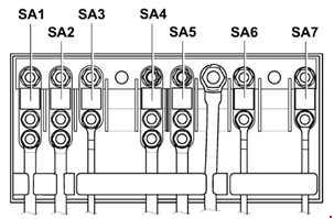
Transcript
| 1 | 150/180A – Generator |
| 2 | 80A Electric motor of the electric power steering |
| 3 | 50/80A Radiator fan control unit |
| 4 | 80/100A Thermal fuse 1 seat adjustment, Left/right fuse block |
| 5 | 80A Fuse box right (until April 2008), Thermal fuse 1 driver’s seat adjustment |
| 6 | 80/100A Fuse box left/right |
| 7 | 40A ABS control unit |
Option 2
Scheme
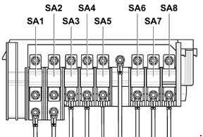
Description
| 1 | 150A – Generator |
| 2 | 80A Electric motor of the electric power steering |
| 3 | 50/80A Radiator fan control unit |
| 4 | 60A Thermal fuse 1 seat adjustment, Left/right fuse box |
| 5 | 60/80A Thermal fuse 1 seat adjustment, Left/right fuse box |
| 6 | 80/100A Fuse box left/right |
| 7 | 60A Charging cable for the second battery, 100A – heating element of the additional air heater, High power heating relay |
| 8 | 40A ABS control unit |
In vehicles with diesel engines, the glow plug control unit will be located under the fuse and relay box.
Block in the luggage compartment
Some models with a battery installed in the luggage compartment have additional protection elements in the form of fuses and relays.
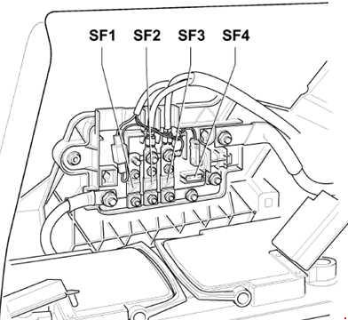
Appointment
| 1 | 30A Fuse box left/right |
| 2 | 80A Fuses in the switchboard |
| 3 | 125A Power supply of the switching unit |
| 4 | 5A On-board network control unit |
In the left part of the luggage compartment behind the side trim, there may be several relay elements: 70A – Limousine, 60A – Variant