Volkswagen Caddy is a light commercial vehicle, produced in two body styles: van and minivan, in 4 generations since 1980. In our material you will find a description of fuses and relays for the third generation Volkswagen Caddy (Caddy Typ 2K), which was produced in 2004, 2005, 2006, 2007, 2008, 2009, 2010, 2011, 2012, 2013 and 2014. We will also show where the blocks are located, their photos and diagrams. We will separately highlight the fuse responsible for the cigarette lighter.
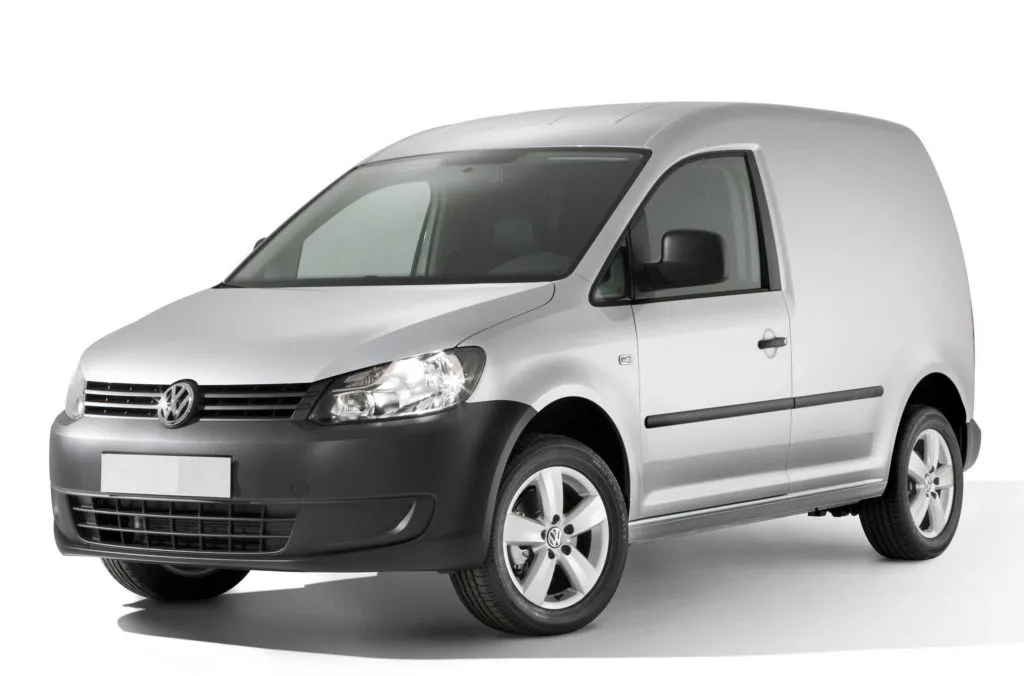
Due to the fact that the Volkswagen Caddy was produced with different body variants, trim levels and electrical equipment, and also underwent a facelift in 2010, there is no single general description for all units. We will present for your reference the most common ones.
General arrangement of blocks Volkswagen Caddy
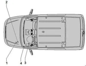
- Fuse links in the fuse block (A -SA-), additional relay block under the switch block
- Fuses and relays in the switchboard (B -SB-)
- Fuse and relay block under the front panel on the left (C -SC-)
- Relay in the footwell
Blocks under the hood Volkswagen Caddy
Fuse and relay block
Located next to the battery. Consists of high-power fuses connected to the battery and a compartment with fuses and relays.
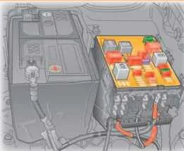
Option 1
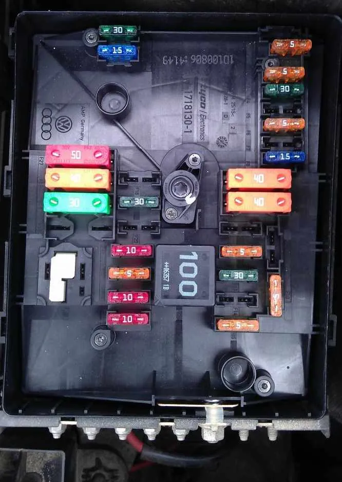

| № | A | Description |
|---|---|---|
| Fuses | ||
| 1 | – | |
| 2 | 30A | Mechatronic unit of DSG gearbox |
| 3 | 5A | Control unit for battery monitoring On-board network control unit |
| 4 | 20A | ABS control unit ABS hydraulic unit |
| 5 | 15A | Mechatronic unit of DSG gearbox |
| 6 | 5A | Instrument cluster control unit Steering column control unit |
| 7 | 40A | Power supply relay terminal 15 Fuse block C -SC- |
| 8 | 15A | Control unit with radio navigation system display Main unit Voltage stabilizer Control unit with radio navigation system display Main unit Fuse 57, 58 in fuse block C -SC- |
| 9 | 5A | Mobile phone control electronics control unit |
| 10 | 5A | Main relay Engine control unit Engine electronic components power supply relay |
| 11 | 30A | Auxiliary heater control unit |
| 12 | 5A | Data bus diagnostic interface |
| 13 | 15A/ 30A | Engine control unit (petrol) Engine control unit (diesel) |
| 14 | 15A/ 20A | Fuel pressure regulator (diesel) Ignition coil |
| 15 | 5A | Heating relay Fuel pump relay Electric fuel pump relay 2 Glow plug control unit 10A Lambda probe heating element, gas supply valve 15A High pressure valve, Gas supply valve |
| 16 | 30A | On-board network control unit, battery, ABS, headlight and turn signal lamps |
| 17 | 15A | Horn relay |
| 18 | 30A | Control unit for special vehicles |
| 19 | 30A | Wiper motor control unit |
| 20 | 10A | Fuel tank shut-off valve Circulation pump OP |
| 21 | 30A /15A | Lambda sensor heating element (diesel) Fuel pump control unit, Lambda sensor heating element |
| 22 | 5A | Clutch pedal position sensor Brake light switch |
| 23 | 5A 10A 15A | Additional cooling system pump relay Air flow meter (diesel vehicle) Boost pressure limit solenoid valve (diesel vehicle) EGR radiator switchover valve (diesel vehicle) Gas control unit Shut-off valve relay Gas high-pressure valve Fuel pressure regulator |
| 24 | 10A | Radiator fan control unit Secondary air pump relay Additional cooling system pump relay Adsorber solenoid valve 1 Coolant control valve Intake manifold geometry change valve Coolant circulation pump 2 Cylinder injectors |
| 25 | 40A | ABS hydraulic pump ABS control unit |
| 26 | 30A | On-board network control unit, headlight and turn signal lamps |
| 27 | 40A/ 50A | Secondary air pump motor Glow plug control unit |
| 28 | – | |
| 29 | 30/ 50A | Fuses in fuse block C -SC- |
| 30 | 50A | Fuse block C -SC- |
| Relay | ||
| A1 | Main relay, Relay for power supply of electronic engine components | |
| A2 | Secondary air pump relay, Additional cooling system pump relay, Gas shut-off valve relay, Jumper | |
Option 2
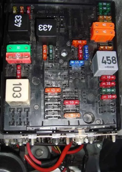
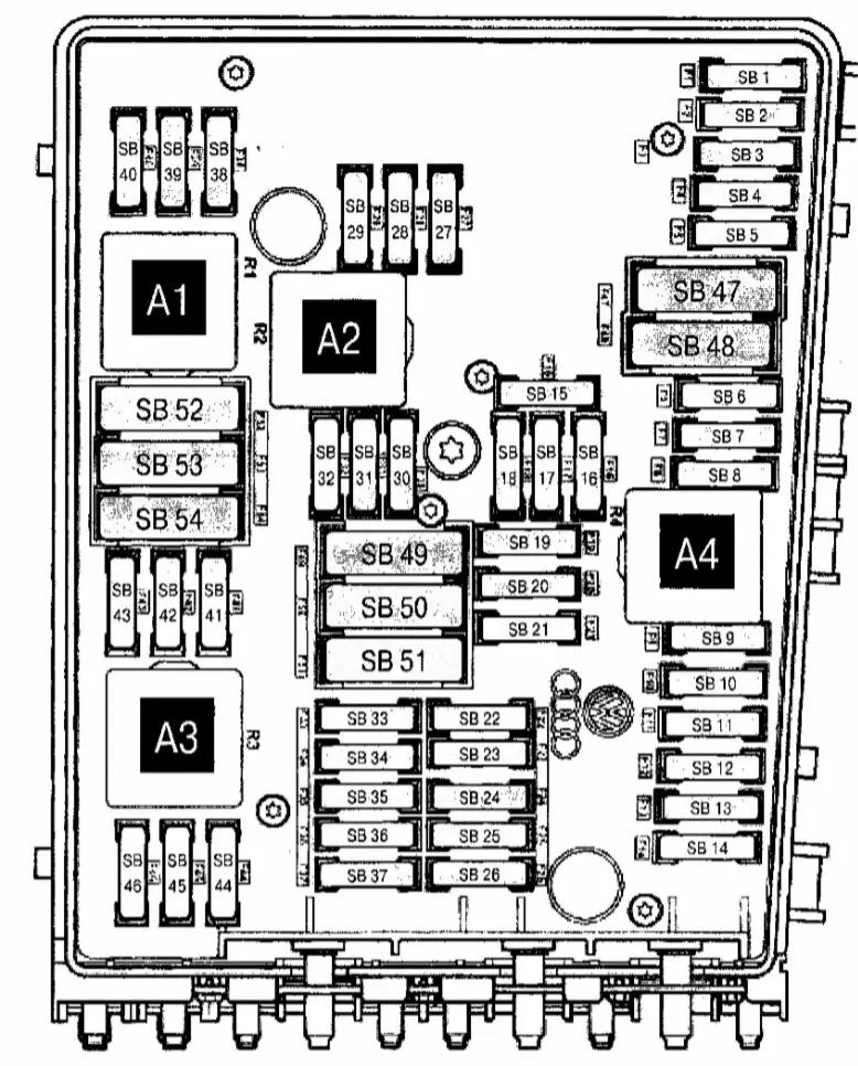
| № | A | Marking |
|---|---|---|
| 1 | 30A | ABS control unit |
| 2 | 30A | ABS control unit |
| 3 | not used | |
| 4 | 5A | on-board network control unit |
| 5 | 20A | signal, horn relay |
| 6 | 20A | ignition coil |
| 7 | 5A | brake pedal switch, engine control units, clutch pedal position sensor |
| 8 | 10A | exhaust gas recirculation valve, absorber solenoid valve 1, radiator fan control unit, intake air flap drive motor |
| 9 | 10A | fuel pump relay (BDJ, BJB) |
| 10 | 10A | exhaust gas recirculation valve, boost pressure limit solenoid valve, exhaust gas recirculation radiator switching valve |
| 11 | 25/30A | Motronik control unit (BCA, 8GU), diesel engine injection system control unit (BDJ. BJB) |
| 12 | 10A | lambda probe (LSA), lambda probe after the catalyst (LSA) |
| 13 | not used | |
| 14 | not used | |
| 15 | 40A | starter (power circuit 50) |
| 16 | 15A | steering column control unit |
| 17 | 10A | instrument cluster control unit |
| 18 | not used | |
| 19 | 15A | R radio, control unit with radio navigation system display |
| 20 | 10A | control unit of the electronics of the mobile phone control |
| 21 | not used | |
| 22 | not used | |
| 23 | not used | |
| 24 | 10A | diagnostic data bus interface |
| 25 | 25A | reserve, 10A Motronik control unit |
| 26 | 5A | power supply relay terminal 30 |
| 27 | 10A | heating resistor of the engine crankcase ventilation system |
| 32 | 40A | glow plugs 1, 2, 3 |
| 33 | 15A | glow plug 4, fuel pump |
| 34 | not used | |
| 35 | not used | |
| 35 | not used | |
| 37 | not used | |
| 38 | 10A | headlight range adjuster actuator motor |
| 39 | 5A | oil level and temperature sensor, instrument cluster control unit |
| 40 | 20A | Fuse power supply in the passenger compartment |
| 41 | 5A | fuel pump relay |
| 42 | 10A | glow plug relay, air flow meter |
| 43 | not used | |
| 44 | not used | |
| 45 | 15A | lambda probe |
| 46 | not used | |
| 47 | 40A | On-board network control unit, Left headlight (vehicles with central locking) |
| 48 | 40A | On-board network control unit, Right headlight (vehicles with central locking) |
| 49 | not used | |
| 50 | 50A | glow plugs |
| 51 | 40A | glow plugs, secondary air pump relay, secondary air pump motor |
| 52 | not used | |
| 53 | 25A | driver’s door control unit, front passenger’s door control unit |
| 54 | 50A | radiator fan control unit |
The glow plug control unit is located separately under the unit itself.
High power fuse links Volkswagen Caddy
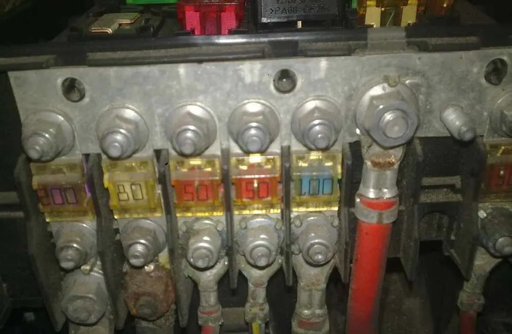
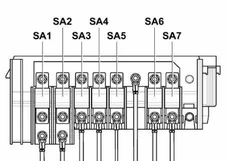
| № | A | Marking |
|---|---|---|
| 1 | 150/ 200A | Generator |
| 2 | 50/ 80A | Power steering control unit |
| 3 | 50A | Radiator fan control unit |
| 4 | 80A | Contact relief relay X or Fuse block C -SC- |
| 5 | 80A | Not used or Fuse block C -SC- |
| 6 | 100A | Fuse block C -SC- or 40A – low-power heating relay |
| 7 | 80A | High power heating relay or Fuse block C -SC- |
Blocks in the cabin Volkswagen Caddy
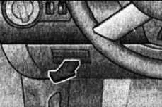
The main unit with fuses and relays is located under the instrument panel on the driver’s side.
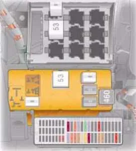
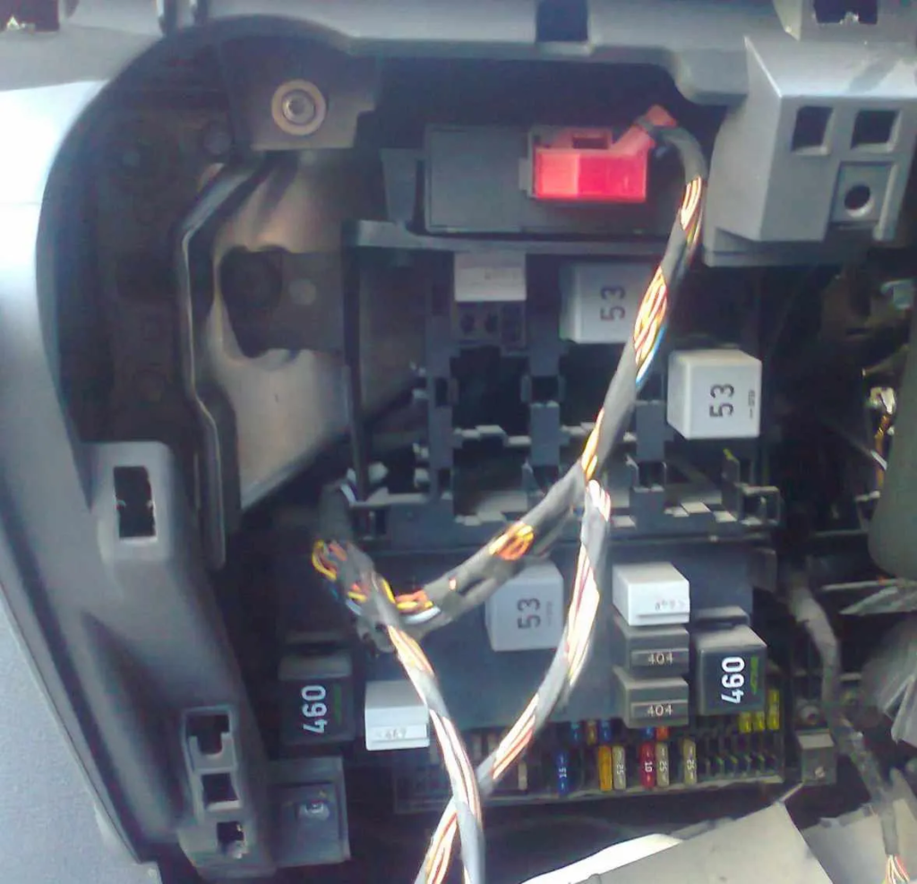
Fuse block Volkswagen Caddy
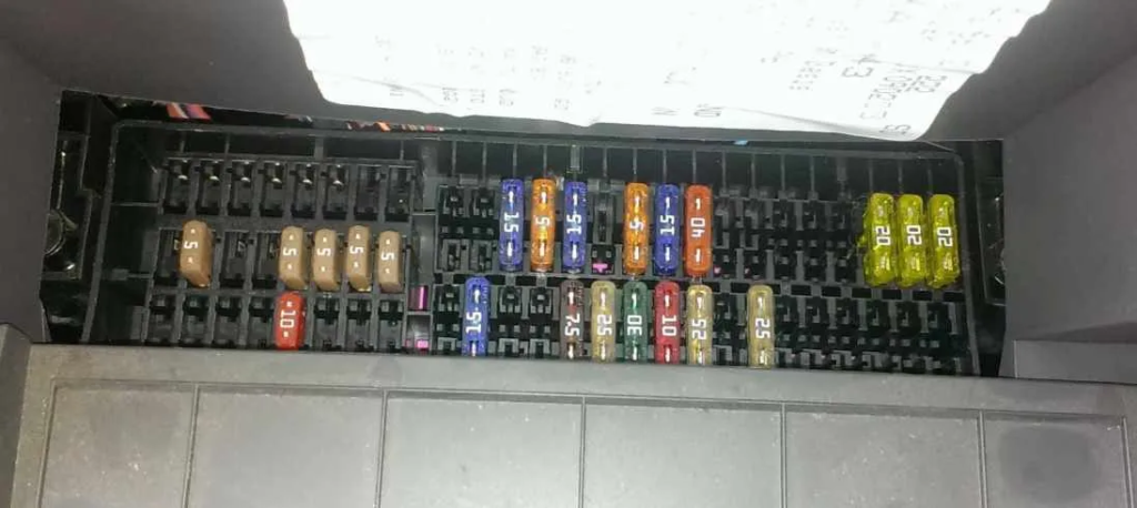
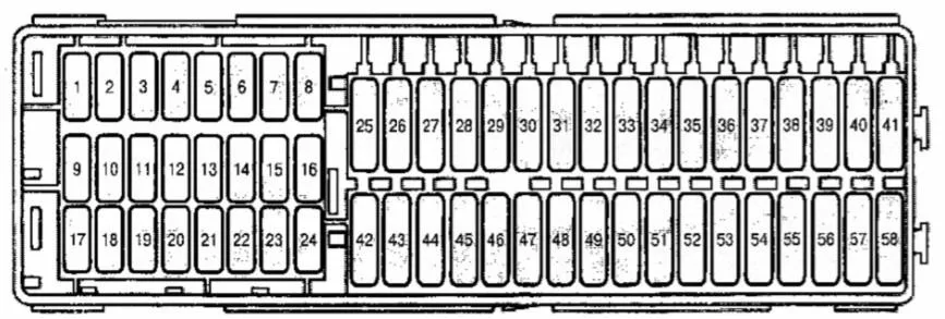
| № | A | Marking |
|---|---|---|
| 1 | 15A | engine start button |
| 2 | 5A | trailer recognition control unit |
| 3 | 5A | heater switch and operating mode selector, high pressure sensor |
| 4 | 5A | control unit of the electronics of the mobile phone control |
| 5 | 15A | air flow meter |
| 6 | 5A | airbag control unit |
| 7 | driver and passenger seat heating regulator, air conditioning control unit | |
| 8 | 5A | heating resistor of the left and right windshield washer jets |
| 9 | 5A | airbag control unit, power steering unit |
| 10 | 5A | control unit for mobile phone control electronics, 10A reversing light switch |
| 11 | 10A | power steering control unit |
| 12 | not used | |
| 13 | not used | |
| 14 | 5A | ASR switch, ASR and ESP off button, ABS control unit with EDS |
| 15 | 10A | reversing light switch, relay for operation in auxiliary heater mode (from May 2004) |
| 16 | 5A | diagnostic data bus interface |
| 17 | 7.5A | left side marker light and rear fog light bulb (vehicles without central locking) |
| 18 | not used | |
| 19 | not used | |
| 20 | not used | |
| 21 | 5A | selector |
| 22 | 5A | radio signal receiving device for additional liquid heater |
| 23 | 10A | brake light switch, left brake light bulb, right brake light bulb, upper brake light bulb, ABS control unit |
| 24 | 10A | light switch, air conditioning control unit, diagnostic connector (T16/16) |
| 25 | 30A | driver’s seat heating control unit, front passenger’s seat heating control unit |
| 26 | 10A | engine control units, injectors |
| 27 | 15A | rear window wiper motor (from May 2004) |
| 28 | 5A | light switch (vehicles with central locking) |
| 30 | 20A | fog light switch, lighting switch |
| 31 | 25A | relay for operation in autonomous heater mode (until April 2004), after – on-board network control unit |
| 32 | 15A | washer pump |
| 33 | 40A | heater switch and operating mode selector, air conditioning control unit |
| 34 | not used | |
| 35 | 40A | supply fan, relay for operation in autonomous heater mode |
| 36 | not used | |
| 37 | 15A | right dipped beam headlight bulb (vehicle without central locking) |
| 38 | 15A | left dipped beam headlight bulb (only vehicles without central locking) |
| 39 | not used | |
| 40 | 20A | trailer recognition control unit |
| 41 | 20A | TSU socket |
| 42 | 15/ 30A | 12 V socket (next to the parking brake lever), socket (12 V) on the left in the luggage compartment |
| 43 | 15A | electric fuel pump relay 2 (BCA, BGU), fuel pump |
| 44 | 5A | interior security system sensor, vehicle tilt sensor |
| 45 | 5A | antenna selection control unit |
| 46 | 7.5A | on-board network control unit |
| 47 | 25A | cigarette lighter |
| 48 | 20A | headlight cleaning system relay, headlight washer pump |
| 49 | 10A | driver’s door control unit, front passenger’s door control unit |
| 50 | 25A | central control unit for comfort systems |
| 51 | 30A | seat heating control unit |
| 52 | 25A | supply fan relay, on-board network control unit |
| 53 | 25A | central control unit for comfort systems / 30A Lamps |
| 54 | not used | |
| 55 | not used | |
| 56 | not used | |
| 57 | 30A | emergency data logger |
| 58 | not used |
Fuse number 47 at 25A is responsible for the cigarette lighter. Please note that the fuses for additional sockets are located separately.
Relay block Volkswagen Caddy
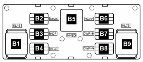
| № | Description |
|---|---|
| B1 | J681 – relay 2 power supply terminal 15 (460) |
| B2 | not used |
| B3 | not used |
| B4 | J689 – relay 2 power supply terminal 30 (449) |
| B5 | J9 – rear window heating relay (53) |
| B6 | J413 – Horn Relay (449) |
| B7 | J729 – dual washer pump relay 1 (395/404) |
| B8 | J730 – dual washer pump relay 2 (395/404) |
| B9 | J59 – contact X unloading relay (460) |
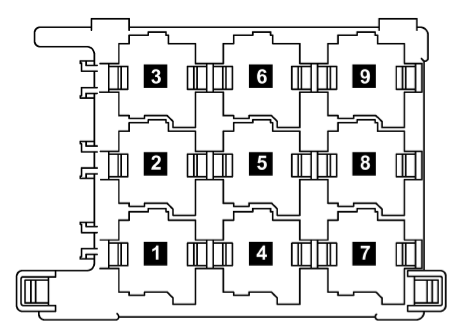
| № | Marking |
|---|---|
| 1 | Headlight cleaning system relay (646) |
| 2 | Fuel pump relay (646), headlight cleaning system relay (53) |
| 3 | Power supply relay terminal 50 (645), Starter relay 1 (645) (from November 2011), Fuel pump relay (449) |
| 4 | Relay for operation in the autonomous heater mode (645) (until October 2011), Relay for unloading contact X (644) (from November 2011), Relay for heating the rear window (645) (from May 2012) |
| 5 | Fuel supply relay on the pressure line (646), Fuel pump shutdown relay (404) |
| 6 | Starter relay 2 -J907- (507) (from November 2011) |
| 7 | High power heating relay (644) (until October 2011), Terminal 15 power supply relay (645) (from November 2011), Auxiliary heater operation relay (53) |
| 8 | Electric fuel pump relay 2 (646), Fuel pump cut-off relay (646) |
| 9 | Low power heating relay (645) (until October 2011), Rear window heating relay (645) (from November 2011), Contact X relief relay (from May 2012) |
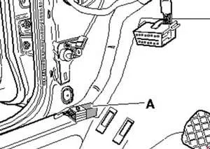
Individual relays may be located in the driver’s footwell, such as the taxi’s remote control anti-theft alarm control unit or the roof fan 1 switching relay.