In the following post we present diagrams and locations of fuse boxes and relays for Volkswagen Beetle from years: 2011, 2012, 2013, 2014, 2015, 2016, 2017, 2018, 2019. The fifth generation Volkswagen Beetle, produced from 2011 to 2019, was an improved version of the New Beetle.
Checking and replacing fuses
As you know, fuses protect against overloading the electrical system of our cars. When one of the components stops working, it is most likely that the circuit breaker has tripped or the fuse has blown. Therefore, before repairing, you should check the fuse responsible for the given element. A blown fuse will be indicated by a melted or completely broken tape inside the fuse.
Remember this before replacing the fuse!
- remove the key from the ignition
- check if everything has been turned off
- always replace fuses with the same amperage.
Passenger compartment
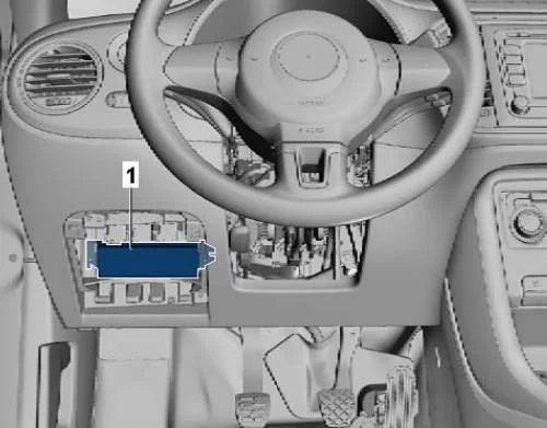
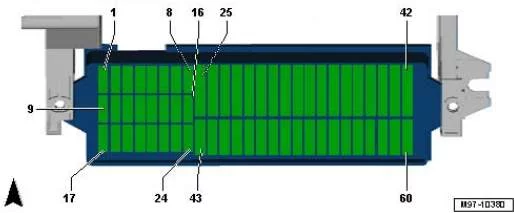
Description
- 5A – BU 2 blind spot control
- 10A – Emergency call module and communication unit control unit
- 5A – BU combination of devices
- 5A – Receiving – transmitting a telephone device
- 10A – Instrument cluster control unit, on-board power supply control unit, left fog light
- 10A – Unlock button on the tailgate handle, reversing camera
- 5A – dimmer for switches and instrument panel lighting, license plate lighting
- 10A-Windscreen washer pump
- 5A – Airbag control unit, front passenger airbag deactivation warning lamp, seat occupancy recognition control unit
- 15A – Intermittent wiper switch
- 5A – Light switch
- reserve
- 5A – Start-stop mode button, Folding mirror switch, Tire pressure indicator button, Reversing light switch, High pressure sensor, Air pollution sensor, Heater control unit, Parking assist control unit, Vehicle tracking system control unit, Electrochromic interior mirror, Washer nozzle heating resistor
- 10A – Cruise control switch, Tiptronic switch, Oil level and temperature sensor, Additional instruments, ABS controller, Instrument cluster controller, Power steering controller, Steering column controller, Voltage regulator, Diagnostic data bus interface, Fuel pump controller, Gear shift lever sensor controller, Engine control unit, Crankcase ventilation heater resistor
- 5A – dimmer for switches and instrument panel lighting, air flow meter, vibration damping system control unit, headlamp range control actuator, connector, 16-pin, diagnostic connector.
- 5A – Engine Control Unit
- 10A – Interior monitoring system sensor, vehicle tilt sensor, alarm siren
- 15A – Left dipped beam lamp
- 15A – Right dipped beam lamp
- 10A – Tiptronic switch, heater control unit, automatic
gearbox control unit, Climatronic control unit, air conditioning control unit, gear lever sensor control unit, ignition key removal lock solenoid - 15A – On-board Power Control Unit
- 5A – Ignition and starter switch, Vehicle tracking control unit
- 10A – Rain and light sensor, On-board power supply control unit, Telephone transceiver, Control unit for emergency call module and communication unit, Connector, 16-pin -T16-, diagnostic connector, Additional devices
- 10A – On-board power supply control unit, Access and start authorization control unit, Electric steering column lock, Data bus diagnostic interface,
- 10/25A Automatic gearbox control unit, multi-function switch, DSG mechatronic unit
- 30A – Brake system vacuum pump
- reserve
- 25A – Terminal 75 Power Relay 1
- 5A – On-board Power Control Unit
- 20A – Blocking Diode, Cigarette Lighter, 12V Socket.
- 30A – Light switch
- 15A – Fog light switch
- 40A – Heater Control Unit, Air Conditioning Control Unit
- 10/15A – instrument panel control unit, on-board power supply control unit, left main beam lamp, right main beam lamp, headlights
- 1A – Steering column control unit
- 30A – On-board Power Control Unit
- 5A – Left daytime lighting module lamp
- 5A – Right daytime running light module lamp
- 30A – Manual dipped beam and flasher relay (main beam)
- reserve
- reserve
- reserve
- 30A – Front passenger door control unit
- 30A – On-board Power Control Unit
- 30A – Driver’s door controller
- reserve
- 20A – Fuel Pump Relay
- 30A – On-board Power Control Unit
- 40A – Supply fan control unit
- 30A – Front seat heating control unit
- 30A – Sliding sunroof control unit
- 20A – On-board Power Control Unit
- 20A – On-board Power Control Unit
- 25A – Automatic transmission control unit
- 20A – light switch, dipped beam and light switch (including main beam)
- 20A – On-board Power Control Unit
- 25A – Control unit with display for radio navigation system, main unit
- 10A – Reducing agent dosing system relay
- reserve
- reserve.
Engine compartment
It is located next to the battery, under the protective cover.
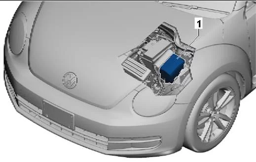
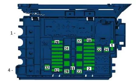
Description
High-capacity fuse links
- 200A – Generator
- reserve
- 80A – Power steering control unit
- 80A – Fuses
Description
- reserve
- 20/30A – Engine Control Unit
- 5A – Radiator fan control unit
- 15A – Lambda – probe
- 10A – Lambda sensor, Electric fuel pump relay, Heating resistance relay, Turbocharger pressure limiting solenoid valve, Crankcase ventilation heating resistor, Camshaft 1 control valve, Turbocharger bypass valve, Intake manifold flap valve, Recirculation cooler switchover valve, Diagnostic fuel pump
- 10A – Fuel pump relay, secondary air pump relay,
engine power supply relay, turbo pressure limiting solenoid valve, adsorber solenoid valve, intake manifold flap valve, oil pressure regulating valve - 20 / 30A – Throttle body, Ignition coil 1 with output stage, Ignition coil 2 with output stage, Ignition coil, Fuel pressure regulator, Fuel metering valve.
- 10A – Air mass meter, Fuel pump relay, Boost pressure limiting solenoid valve, Adsorber solenoid valve 1, Camshaft adjuster valve 1, Exhaust gas recirculation valve 2, Turbocharger bypass valve, Fan drive solenoid clutch, Oil pressure regulating valve, Coolant regulating valve, Coolant circulation pump 2
- 10A – Relay for pumping coolant after switching off. Engine control unit, Glow plug control unit, Low heating power relay, High heating power relay, Additional coolant pump relay, Engine electronics power supply relay, Fuel pressure regulator, Coolant circulation pump 2
- 5A – Clutch pedal position sensor, brake light switch
- reserve
- reserve
- 30A – Voltage regulator, Radio navigation system display control unit, Navigation system control unit,
Main unit - 10A – Motronic power supply relay, terminal 30 power supply relay, engine control unit
- 10A – Alarm Siren Relay
- 40A – Amplifier
- 15 / 30A – DSG gearbox mechatronic unit
- 15A – Block Mechatronik KP DSG
- 5A – On-board power control unit (battery)
- 30A – On-board Power Control Unit
- 40/50A – Heating element for additional air heater, Secondary air pump motor
- 40A – Heating element of the additional air heater
- reserve
- 40/50A – Terminal 75 Power Relay 1
- 40A – Terminal 15 Power Relay
- 50A – Glow plug control unit
- 50A – Radiator fan control unit
- 20/30A – Fuel pump relay, engine electronics power relay
- reserve
- 40A – ABS control unit
- 40A – ABS control unit
- 40A – Additional air heater heating element, Secondary air pump motor