Type 1
These diagrams are mainly suitable for the 5th generation and models with the 4HF1 and 4HG1 engine.
Fuse box
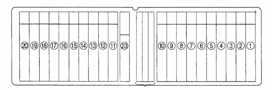
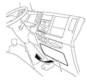
It is located in the panel and is closed with a protective cover, on the back of which the current diagram with a description of the elements will be applied.
Description
| 1 | 25А / 15А Heater fan motor, heater fan resistor, temperature switch, pressure switch, air conditioner shutdown relay, air conditioner relay, thermostat, e / p valve of the speed increase system XX (FICD) |
| 2 | 10A Air conditioning switch, air conditioning relay, pressure switch, air conditioning compressor electromagnetic clutch, XX speed increase valve (FICD), thermostat |
| 3 | 10A Starter relay, Start lock switch |
| 4 | 15A Cigarette lighter , radio |
| 5 | 10A Headlight (right), headlight switch relay |
| 6 | 10A Headlight (left), Headlight switch relay, Turn signal relay, Turn signal |
| 7 | 15A Radio and clock, interior lights, interior light switch, door limit switches, reversing warning buzzer, door lock switch, central locking relay, electric door locks, central locking controller, speedometer |
| 8 | 15A Hazard warning light switch, horn, horn relay, horn switch, turn signals |
| 9 | 15A Dimension relay, lights, fog light switch, fog lights, light switch, rear fog light switch, rear fog light relay |
| 10 | 10A Brake light switch, brake lights, selector lock controller |
| 11 | 15A Wiper and Washer Control Switch, Wiper Motor, Washer Motor, Wiper Interval Relay |
| 12 | 10A Mountain brake control relay, automatic transmission electronic control unit, “OD OFF” indicator, “NO LOAD” indicator, condenser fan motor relay, reverse gear warning buzzer, reversing light switch, reversing lights, start lock switch, starter relay, engine starting aid (QOSIII) controller, engine starting aid controller (QOSII), glow plug relay No. 1, glow plug relay No. 2, glow plug indicator, coolant temperature gauge, temperature sensor, vehicle speed sensor, instrument cluster, window lifter relay, turn signal relay, 4WD control system switch, 4WD system relay, four-wheel drive control system electro-pneumatic valve |
| 13 | 10A / 15A Fuel heater |
| 14 | 15A Rear heater, rear heater switch |
| 15 | 10A Exhaust brake switch, exhaust brake control relay, exhaust brake solenoid valve, exhaust brake solenoid clutch, accelerator pedal |
| 16 | 10A Fog Light Switch, Fog Lights, ECU |
| 17 | 10A Turn signals, turn signal switch |
| 18 | 15A Alternator, Charging Relay, Starting Aid Controller (QOSIII) |
| 19 | 10A Electric engine switch, fuel shut-off solenoid valve |
| 20 | 10A Headlight range control switch, headlight range control electric drive |
| 23 | 15A Turn signal amplifiers, turn signal relays |
Relay and fuse box
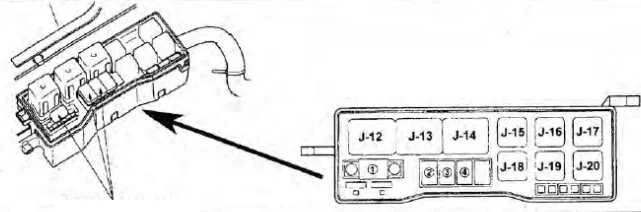
It is located on the left side at the rear of the cabin or behind the left fender. The high-capacity fuses or fuses and separate relays will be located there.
Relay box
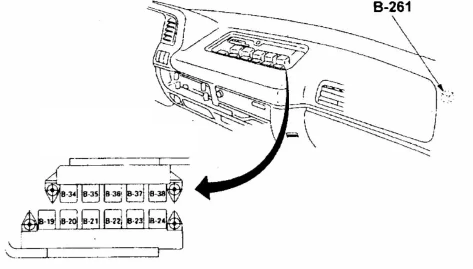
Individual elements may be outside of blocks. For example, B-261.
Description
| B9 | Wiper Interval Changing System Relay (BREAK) |
| B-19 | Charging relay |
| B-19 | (FEE) |
| B20 | Headlight relay |
| B20 | (HEAD) |
| B21 | Relay for air conditioning, heating and ventilation (HEATER & AIR CON.) |
| B-22 | Dimensional relay |
| B-23 | Combination switch relay |
| B-23 | (RESISTOR) |
| B-24 | Horn relay |
| B-24 | (HORN) |
| B-34 | Rear fog light relay |
| B-34 | (REAR FOG LAMP) |
| B-35 | Low beam relay |
| B-35 | (LIGHT OF THE DAY) |
| B-35 | Rear fog light relay |
| B-35 | (FRONT FOG LAMP) |
| B-36 | Power Window Relay |
| B-36 | (Power windows) |
| B-37 | Pressure switch relay |
| B-37 | (THERMO-CONDITIONING/AIR CONDITIONING) |
| B-38 | Mountain brake relay |
| B-38 | (OUTPUT BRAKE) |
| J-12 | Starter relay |
| J-12 | (STARTER) |
| J-13 | Glow plug relay |
| J-14 | Glow plug relay |
| J-16 | Capacitor heating control relay (CDS). |
| J-18 | Exhaust brake control relay |
| J-18 | (OUTPUT BRAKE CONTROL) |
| J-19 | 4WD system relay |
| J-19 | Air Conditioner Shutdown Relay |
| J-19 | (AIR CONDITIONING CUT OFF). |
| J-20 | Turn signal relay (MARKER LAMP) |
Type 2
This type of fuse boxes is used in the 6th generation and in cars with 4HG1-1, 4JJ1, 4HK1 engines.
Box in the car
The main fuse and relay box is also located in the cabin on the passenger side dashboard.
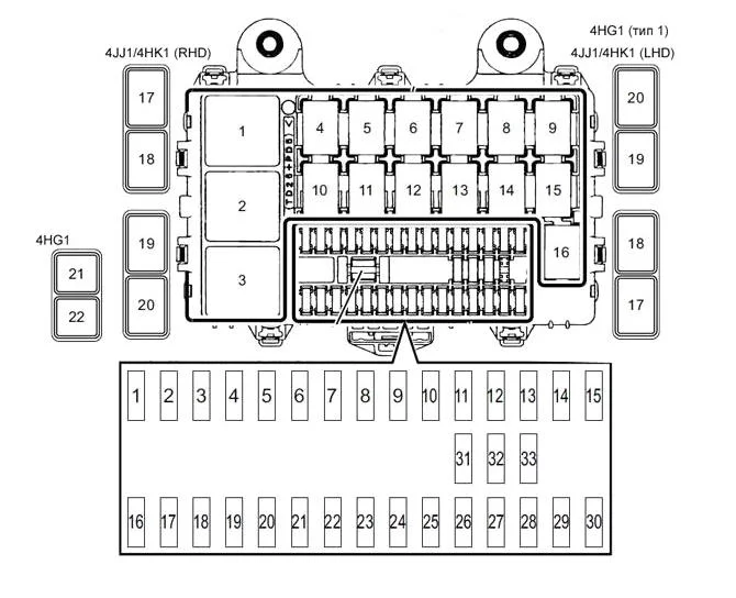
Description
| 1 | Power take-off 20A (battery) |
| 2 | 20A Rear right window lifter |
| 3 | 15A Interior lighting, audio system |
| 4 | 15A Door locks |
| 5 | 10A Fog lights |
| 6 | 20A Electric windows |
| 7 | 10A Anti-lock Braking System (ABS) |
| 8 | 15A Wiper |
| 9 | 10A Low beam (left headlight) |
| 10 | 10A Engine Management System (Battery) |
| 11 | 10A Low beam (right headlight) |
| 12 | 10A Brake lights |
| 13 | 15A Ignition (IGN2) |
| 14 | 10A High beam (left headlight) |
| 15 | 10A High beam (right headlight) |
| 16 | 10A Power take-off (KEY ST) |
| 17 | 10A Starter |
| 18 | 15A Ignition (IGN1) |
| 19 | 10A Airbags |
| 20 | 10A Engine Control Module (ECM) |
| 21 | 10A Instruments |
| 22 | Lights 10A (batteries) |
| 23 | 15A Audio system (ACC) |
| 24 | 15A Exterior mirror drive |
| 25 | 15A Horn |
| 26 | 15A Direction indicators, hazard warning lights |
| 27 | 10A Marker lights |
| 28 | 10A Backlight |
| 29 | 10A Side cornering lights, rear fog light |
| 30 | 20A Heater fan motor, air conditioner 10A |
| 31 | 20A lighter |
| 32 | Reserve |
| 33 | Reserve |
| Relay | |
| 1 | Brake lights |
| 2 | Heater fan motor |
| 3 | Ignition Switch (KEY ON) |
| 4 | 4JJ1, 4HK1: Door locks (locking) |
| 4HG1: Reserve place | |
| 5 | 4JJ1, 4HK1: Rear fog light |
| 4HG1: Reserve place | |
| 6 | Basic wiper mode |
| 7 | Sound signal |
| 8 | Wiper modes (HIGH/LOW) |
| 9 | Fog lights |
| 10 | Power take-off (MAIN) |
| 11 | 4JJ1, 4HK1: Door locks (opening) |
| 4HG1: Reserve place | |
| 12 | Electric windows |
| 13 | Headlights (dipped beam) |
| 14 | 4JJ1, 4HK11), 4HG1: All-wheel drive |
| 4HK12): Engine brake control (models with ABS) | |
| 15 | Headlights (high beam) |
| 16 | Marker lights |
| 17 | 4JJ1, 4HK11): PTO solenoid valve (manual transmission models) |
| 4HK12): Spare seat | |
| 4HG1: Engine brake release | |
| 18 | 4JJ1, 4HK11): Power take-off deactivation |
| 4HK12): Spare seat | |
| 4HG1: Engine brake | |
| 19 | 4JJ1, 4HK11): Charging (with engine running) |
| 4JJ1, 4HK11), 4HG1: Transfer case (ignition 1) | |
| 4HK12): PTO solenoid valve (manual gearbox models) | |
| 20 | 4JJ1, 4HK11): electric windows (rear) |
| 4HK12): Power take-off deactivation | |
| 4HG1: Charging (with engine running) | |
| 21 | 4HG1: PTO solenoid valve (manual transmission models) |
| 22 | 4HG1: Power take-off deactivation |
- 1) Cars with 4JJ1/4HK1 engine (models with hydraulic brake system)
- 2) Cars with 4HK1 engine (models with pneumatic brake system)
Box behind the cabin
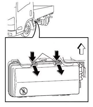
Another fuse and relay box is located on the outside of the car. To access, remove the protective cover.
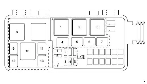
Description
| 1 | 10A Marker lamps |
| 4HG1: Unused | |
| 1 | 15A 4JB1-TC: Fuel heater |
| 2 | 10A Engine Control Module (ECM) |
| 4JB1-TC, 4HG1: Unused | |
| 3 | 10A battery |
| 3 | 15A 4JB1-TC: Battery |
| 4 | 10A Conditioner |
| 4JB1-TC: Not used | |
| 5 | 20A 4HK13): Air conditioning, ABS |
| 4HK11,2), 4JJ1: Not used | |
| 4JB1-TC: Marker lights | |
| 4HG1: Fuel heater | |
| 6 | 15A 4JB1-TC: Air Conditioner |
| 4HK1, 4JJ1: Unused | |
| 4HG1: Engine stop | |
| Relays | |
| 1 | Starter |
| 2 | 4HK1, 4JJ1: Engine Control Module (ECM) |
| 4JB1-TC, 4HG1: Unused | |
| 3 | Glow plugs |
| 4 | Air conditioning compressor |
| 5 | Condenser fan |
| 6 | 4HK1, 4JJ1: Starter motor off |
| 4JB1-TC: Engine brake | |
| 4HG1: Engine stop | |
| 7 | 4HK11), 4JJ1: Side marker lights (models with rear fog lights) |
| 4HK12,3): Engine brake | |
| 4JB1-TC, 4HG1: Fuel heater | |
| 8 | Gear selector |
| 9 | 4WD 4WD (NPS model) |
| 10 | Fuel heater (models with fuel heater) |
| 11 | Distribution box control (NPS model) |
| 12 | Starting the engine (models with fuel heater) |
| 13 | 4HK12,3): Marker lights (models with rear fog lights) |
- 1) Models with 4HK1 engine (Euro 4 emission standard) and hydraulic brake system, models with 4JJ1 engine
- 2) Models with 4HK1 engine (Euro 2 or Euro 3 emission standard) with hydraulic brake system
- 3) Models with 4HK1 engine and pneumatic brake system
- 4) Models with 4JB1-TC engine (type 1)
- 5) Models with 4HG1 engine (type 1)
Type 3
Fits 4JB1 engines. The location of the boxes is the same as type 2.
Box in the car
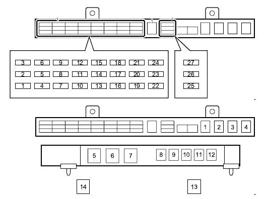
Description
| 1 | Lamps 10A (batteries) |
| 2 | 10A Interior lighting, audio system |
| 3 | 10A Engine brake |
| 4 | 15A Door locks |
| 5 | 15A Fog lights |
| 6 | 25A Electric windows |
| 7 | 10A High beam (left headlight) |
| 8 | 10A High beam (right headlight) |
| 9 | 10A Brake lights |
| 10 | 10A Low beam (left headlight) |
| 11 | 10A Low beam (right headlight) |
| 12 | 10A Marker lights |
| 13 | Lamps 10A (batteries) |
| 14 | Ignition 10A (IGN2) |
| 15 | 10A Starter |
| 16 | 10A Engine stop |
| 17 | Ignition 10A (IGN1) |
| 18 | 10A Reversing lights |
| 19 | 10A Instruments |
| 20 | 15A Audio system (ACC) |
| 21 | Air conditioner 10A |
| 22 | 15A Horn |
| 23 | 15A Direction indicators, hazard warning lights |
| 24 | 25A Wiper |
| 25 | Reserve |
| 26 | Reserve |
| 27 | Reserve |
| Relay | |
| 1 | Marker lights |
| 2 | Headlights (high beam) |
| 3 | Headlights (dipped beam) |
| 4 | Electric windows |
| 5 | Brake lights |
| 6 | Charging (when engine is running) |
| 7 | Ignition Switch (KEY ON) |
| 8 | Engine brake |
| 9 | Basic wiper mode |
| 10 | Wiper modes (HIGH/LOW) |
| 11 | Fog lights |
| 12 | Sound signal |
| 13 | Reserve your spot |
| 14 | Fan motor |
Box behind the cabin
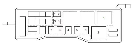
Description
| 1 | 10A 4HG1 (type 2), 4HG1-T: Engine stop |
| 1 | 15A 4JB1-TC (type 2), 4JB1: Power supply |
| 2 | 10A 4HG1 (Type 2), 4HG1-T: Spare battery |
| 2 | 15A 4JB1-TC (Type 2), 4JB1: Fuel heater |
| 3 | 10A 4HG1 (Type 2), 4HG1-T: Fuel heater |
| 3 | 20A 4JB1-TC (type 2), 4JB1: Air Conditioner |
| 4 | 10A 4HG1 (type 2), 4HG1-T: Air Conditioner |
| 4 | 20A 4JB1-TC (Type 2), 4JB1: Condenser fan |
| Relay | |
| 1 | Heating |
| 2 | Starter |
| 3 | 4HG1 (Type 2), 4HG1-T: Engine stop |
| 4JB1-TC (Type 2), 4JB1: Not used | |
| 4 | Fuel heating |
| 5 | Condenser fan |
| 6 | Engine brake |
| 7 | 4JB1-TC (type 2), 4JB1:CSD |
| 4HG1 (Type 2), 4HG1-T: Not used | |