The four-door fastback Volkswagen Arteon has been produced since 2017 and still remains the flagship premium model in the Volkswagen lineup. In this article, you will find detailed diagrams of the fuse blocks of the Volkswagen Arteon 2017, 2018, 2019, 2020, 2021, 2022 and 2023 models, information about the locations of the mounting blocks in the cabin and engine compartment, as well as a full description of the purpose of each fuse and relay.
Created as a successor to the VW CC, the Volkswagen Arteon has a more modern body with frameless doors, an improved electronic architecture and spectacular LED optics. Due to the increased number of electronic components, the car is equipped with additional power circuits and separate fuses, in particular for the door modules, which are located in the main passenger compartment fuse block.
Interior fuse box
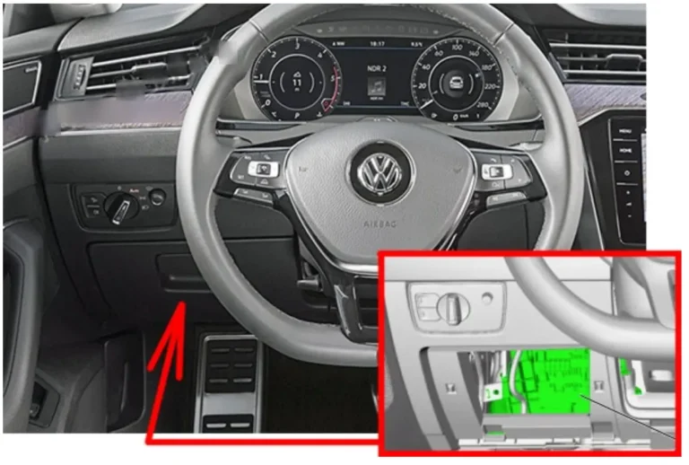
Fuse box location
Left-hand drive: The interior fuse box in the Volkswagen Arteon is located under the dashboard on the driver’s side. Due to the compact layout of the interior elements, access to it is somewhat limited. The fuses and relays are installed very tightly, so for their safe removal it is recommended to use a special plastic puller (tweezers), which is usually attached to the fuse box cover in the engine compartment.
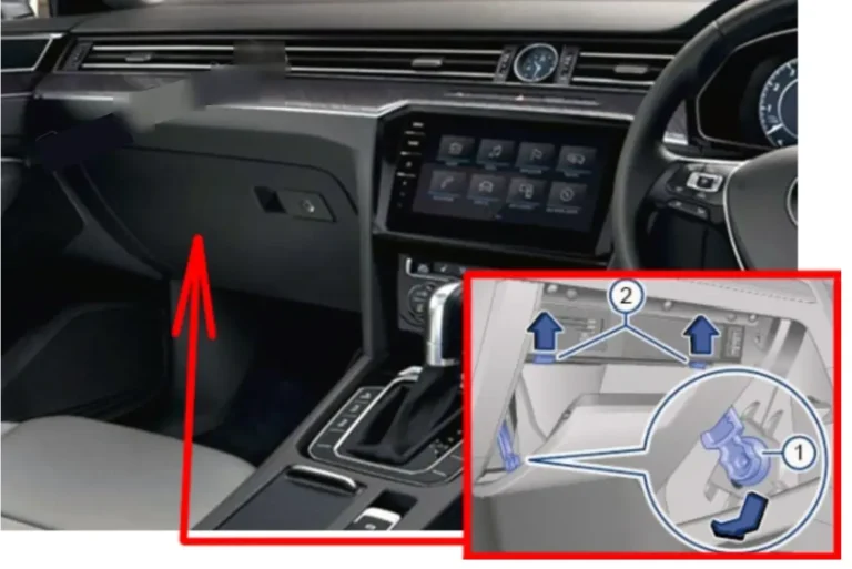
Right-hand drive: This fuse block is located behind a cover on the left side of the glove compartment.
Fuse block diagram
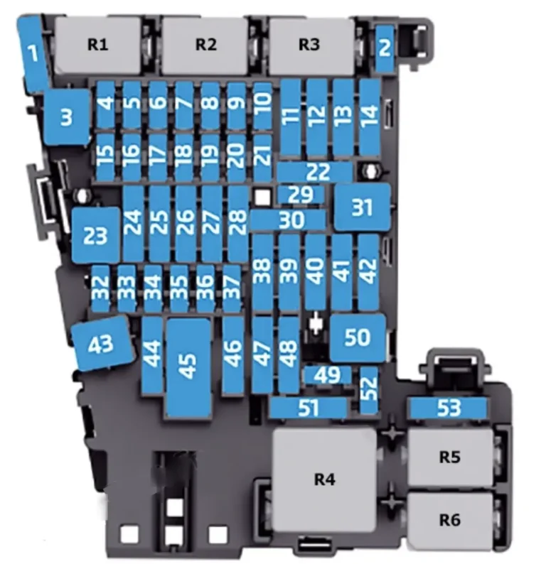
| № | Amperage | Function |
|---|---|---|
| 1 | 30 A | Reagent heater control unit -J891- |
| 2 | 10 A | Steering column electronics unit -J527- |
| 3 | – | – |
| 4 | 7.5 A / 10 A | Alarm siren -H12- |
| 5 | 5 A / 7.5 A | Data bus diagnostic interface -J533- |
| 6 | 5 A / 7.5 A | Selector lever -E313- |
| 7 | 10 A | Heating and air conditioning control unit -EX21-; rear climate control control unit and display -E265-; remote control receiver for additional coolant heater -R149-; rear window heating relay -J9-; analogue clock -Y-; tyre pressure monitoring system control unit -J502- |
| 8 | 7.5 A / 10 A | Light rotary switch -EX1-; electromechanical parking brake button -E538-; rain and light sensor -G397-; diagnostic connector -U31-; alarm sensor -G578-; left background light LED -L181-; right background light LED -L182-; front interior lighting -WX1-; alarm sensor -G578-; cornering light and headlight range control unit -J745-; front left door outline lighting -L251-; rear left door outline lighting -L253-; front right door outline lighting -L252-; rear right door outline lighting -L254- |
| 9 | 5 A / 7.5 A | Steering column electronics unit -J527- |
| 10 | 7.5 A / 10 A | Front information display unit and control unit -J685-; head-up display control unit -J898- |
| 11 | 40 A | On-board power supply control unit -J519- |
| 12 | 20 A | Information electronics control unit 1 -J794-; navigation system control unit -J856- |
| 13 | 25 A | Front left seat belt -NX10- |
| 14 | 40 A | Fresh air fan control unit -J126- |
| 15 | 10 A | Electronic steering column lock control unit -J764- |
| 16 | 7.5 A | Two-way signal booster for mobile phone/data transmission -J984-; USB charging socket 1 -U37-; storage compartment with mobile phone interface -R265-; USB hub -R293- |
| 17 | 7.5 A | Instrument cluster -KX2-; emergency call and communication module control unit -J949- |
| 18 | 7.5 A | Surround view camera control unit -J928-; trunk lid handle -EX37-; rear surround view camera -R246- |
| 19 | 7.5 A | Access and start system interface -J965- |
| 20 | 7.5 A / 10 A / 15 A | Reagent dosing system relay -J963-; vacuum pump relay -J318- |
| 21 | 15 A | All-wheel drive control unit -J492- |
| 22 | 15 A | Trailer recognition control unit -J345- |
| 23 | 20 A / 30 A | Sliding roof adjustment control unit -J245- |
| 24 | 40 A | On-board power supply control unit -J519- |
| 25 | 30 A | Driver’s door control unit -J386-; rear left door control unit -J926- |
| 26 | 30 A | On-board power supply control unit -J519- |
| 27 | 30 A | On-board power supply control unit -J519- |
| 28 | 25 A | Trailer recognition control unit -J345- |
| 29 | 5 A | Remote start system relay -J471- |
| 30 | 10 A | Remote start system relay -J471- |
| 31 | 30 A | Trunk lid control unit -J605- |
| 32 | 10 A | Driver assistance systems front camera -R242-; adaptive cruise control control unit -J428-; parking assist control unit -J446-; lane change assist control unit -J769-; lane change assist control unit 2 -J770- |
| 33 | 5 A / 7.5 A | Airbag control unit -J234- |
| 34 | 7.5 A | Interior mirror -EX5-; power socket relay -J807-; reverse switch -F4-; refrigerant circuit pressure sensor -G805-; air quality sensor -G238-; central switch module in the instrument panel -EX22-; switch module 1 in the center console -EX23-; structure-borne sound control unit -J869-; electromechanical parking brake button -E538- |
| 35 | 7.5 / 10 A | Diagnostic connector -U31- |
| 36 | 5 A / 7.5 A | Front right headlight -MX2- |
| 37 | 5 A / 7.5 A | Front left headlight -MX1- |
| 38 | 25 A | Trailer recognition control unit -J345- |
| 39 | 30 A | Front passenger door control unit -J387-; rear right door control unit -J927- |
| 40 | 20 A | 12V socket -U5-; 12V socket 2 -U18-; 12V socket 3 -U19- |
| 41 | 25 A | Front right seat belt -NX11- |
| 42 | 40 A | On-board power supply control unit -J519- |
| 43 | 40 A | Digital Sound Package control unit -J525- |
| 44 | 15 A | Trailer recognition control unit -J345- |
| 45 | 15 A | Driver’s seat adjustment control unit -J810-; front left seat cushion fan 1 -V514-; front left seat backrest fan 1 -V512- |
| 46 | 30 A | DC/AC converter with socket, 12V–230V -U13- |
| 47 | – | – |
| 48 | – | – |
| 49 | 5 A / 7.5 A | Clutch position sensor -G476-; starter relay 1 -J906-; starter relay 2 -J907- |
| 50 | 40 A | Trunk lid control unit -J605- |
| 51 | 25 A | Rear climate control control unit and display -E265- |
| 52 | 15 A | Electronically controlled damping control unit -J250- |
| 53 | 30 A | Rear window heating relay -J9- |
Relay
| Marking | Function |
|---|---|
| R1 | Reagent dosing system relay -J963- |
| R2 | – |
| R3 | – |
| R4 | Terminal 15 power relay -J329- |
| R5 | Rear window heating relay -J9- |
| R6 | Power outlet relay -J807- |
The following fuses are also located inside the fuse box mount:
| № | Amperage | Function |
|---|---|---|
| A | 15 A | Front right seat adjustment control unit -EX34-; front right seat cushion fan 1 -V518-; front right seat backrest fan 1 -V516- |
| B | 5 A | Remote start system relay -J471- |
| C | 7.5 A | USB charging connector 1 -U37- |
| R1 | – | Remote start system relay -J471- |
Engine compartment fuse box
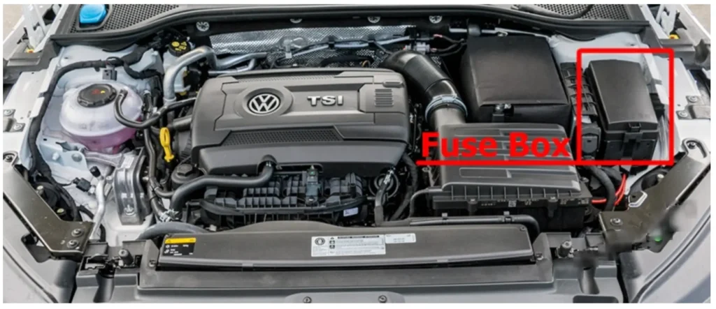
Fuse box location
Fuse block diagram
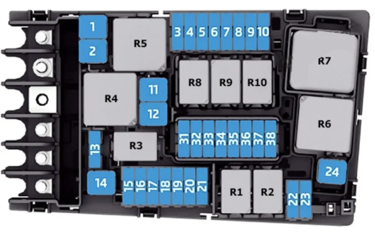
| № | Amperage | Function |
|---|---|---|
| 1 | 25 A | ABS control unit -J104- |
| 2 | 40 A / 60 A | ABS control unit -J104-; ABS hydraulic pump -V64- |
| 3 | 15 A / 30 A | Engine control unit -J623- |
| 4 | 5 A / 7.5 A / 10 A | Radiator fan -VX57-; heater high output relay -J360-; heater low output relay -J359-; oil pressure control valve -N428-; turbocharger air recirculation valve -N249-; intake manifold flap -N316-; piston nozzle cooling valve -N522-; oil level and temperature sensor -G266-; turbine switching valve -N529-; engine component power relay -J757- |
| 5 | 10 A | Fuel pressure control valve -N276-; fuel metering valve -N290-; engine component power supply relay -J757-; turbine switching valve -N529- |
| 6 | 5 A / 7.5 A | Brake light switch -F- |
| 7 | 7.5 A / 10 A / 15 A | Charge air cooling pump -V188-; transmission coolant valve -N488-; coolant shut-off valve -N82-; additional heater pump -V488-; cylinder head coolant valve -N489-; oil pressure control valve -N428-; fuel tank leak detection control unit -J909- |
| 8 | 15 A | Lambda sensor 1 before catalytic converter -GX10-; Lambda sensor 1 after catalytic converter -GX7-; NOx sensor control unit -GX30-; NOx sensor control unit 2 -J881- |
| 9 | 5 A / 10 A | Exhaust system flap control unit -J883-; exhaust system flap control unit 2 -J945-; automatic glow control unit -J179-; crankcase ventilation heating element -N79-; air flow meter -G70-; additional heater pump -V488-; adsorber solenoid valve 1 -N80-; exhaust camshaft control valve 1 -N318-; camshaft control valve 1 -N205- |
| 10 | 15 A / 20 A | Fuel pump control unit -J538- |
| 11 | 40 A / 50 A | Heating element of the additional air heater -Z35- |
| 12 | 40 A | Heating element of the additional air heater -Z35- |
| 13 | 30 A | Additional hydraulic pump 1 for transmission oil -V475- |
| 14 | 40 A | Windshield heating relay -J47- |
| 15 | 15 A | Horn relay -J413- |
| 16 | 20 A | Engine component power supply relay -J757- |
| 17 | 7.5 A | Engine control unit -J623-; ABS control unit -J104-; windshield heating relay -J47- |
| 18 | 5 A / 7.5 A | Battery monitoring control unit -J367-; data bus diagnostic interface -J533- |
| 19 | 30 A | Wiper motor control unit -J400- |
| 20 | 10 A | Alarm siren -H12- |
| 21 | 30 A | Windscreen heating relay 2 -J611- |
| 22 | 5 A / 7.5 A | Engine control unit -J623- |
| 23 | 30 A | Starter -B- |
| 24 | 40 A | Heating element of the additional air heater -Z35- |
| 31 | – | – |
| 32 | – | – |
| 33 | 30 A | Windscreen heating relay 2 -J611- |
| 34 | 30 A | Windscreen heating relay 2 -J611- |
| 35 | 30 A | Wiper motor control unit -J400- |
| 36 | – | – |
| 37 | 30 A | Auxiliary heater control unit -J364- |
| 38 | – | – |
Relay
| Marking | Function |
|---|---|
| R1 | Starter relay 1 -J906- |
| R2 | Starter relay 2 -J907- |
| R3 | Horn relay -J413- |
| R4 | High-power heater relay -J360- |
| R5 | Main relay -J271- (petrol); terminal 30 power relay -J317- (diesel) |
| R6 | Automatic glow plug control unit -J179- (petrol) |
| R7 | Low heater output relay -J359- (diesel) |
| R8 | Engine component power supply relay -J757- (2.0 l petrol engine) |
| R9 | Windshield heating relay -J47- |
| R10 | Windscreen heating relay 2 -J611- |