Toyota Prius V and Toyota Prius + (Plus) station wagon is built on the Toyota Prius platform, which was produced in 2011, 2012, 2013, 2014, 2015, 2016, 2017, 2018 with markings ZVW40 / ZVW41. In this article we will show the location of electronic control units, a description of fuses and relays Toyota Prius 40 41 with block diagrams and their locations. We will highlight the fuse responsible for the cigarette lighter.

There are three fuse boxes in the Toyota Prius V+. The first is located under the panel in the passenger compartment, the second in the engine compartment, and the third in the luggage compartment. Check the assignment of the elements with your diagrams on the block cover.
Blocks in the cabin Toyota Prius 40 41
Arrangement
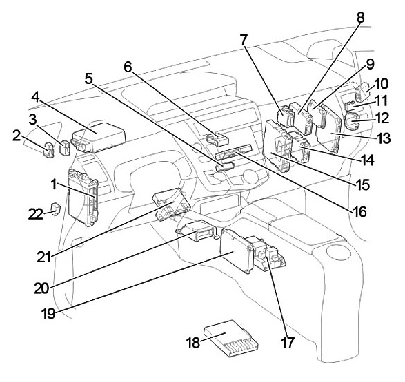
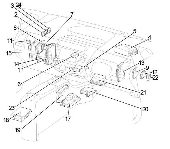
General layout of electronic control units in the cabin
Left-hand drive
Right-hand drive
Description
- Fuse box / main body ECU
- Rear fog light relay
- Bathroom light off relay
- Power steering ECU
- Slag cleaner relay
- Connecting connector (CAN)
- Network gateway ECU
- Seat belt ECU
- Driving support system ECU
- LHD: Oncoming Vehicle Dynamics Controller
- Fuse block
- Headlight correction ECU
- Parking assistance system ECU
- Transmission control ECU
- Power management ECU
- LHD: Expansion module
- High-voltage battery distribution block
- Stereo component amplifier
- Battery voltage sensor
- Airbag ECU
- Air conditioner booster
- Brake light control ECU
- RHD: Double door lock control relay
- RHD: Safety horn relay
Fuse block Toyota Prius 40 41
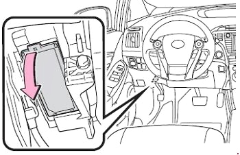
It is located under the dashboard on the left side. To access it, you must remove the protective cover.
Left-hand drive
Right-hand drive
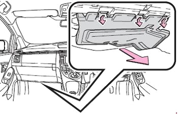
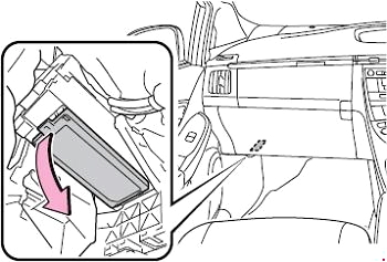
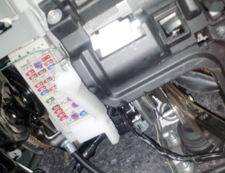
Photo example of execution
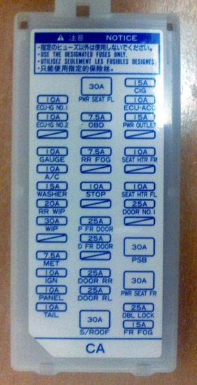
Example of a circuit from the block cover
Scheme
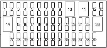
| 1 | CIG 15 A – Socket (cigarette lighter) |
| 2 | ECU-ACC 10 A – Multiplex data transmission system, exterior rear-view mirrors, driver support system, audio system, navigation system |
| 3 | PWR OUTLET 15 A – Socket |
| 4 | – |
| 5 | SEAT HTR FR 10 A – Seat heater |
| 6 | – |
| 7 | SEAT HTR FL 10 A – Seat heater |
| 8 | DOOR NO.1 25 A – Door lock interlock system |
| 9 | – |
| 10 | PSB 30 A – Safety belt with pre-crash system |
| 11 | PWR SEAT FR 30 A — Power seats, lumbar support |
| 12 | DBL LOCK 25 A – RHD: Double locking system |
| 13 | FR FOG 15 A — Before December 2011: Fog lights |
| FR FOG 7.5 A – From December 2011: Fog lights | |
| 14 | PWR SEAT FL 30 A — Power seats, lumbar support |
| 15 | OBD 7.5 A – Diagnostic connector |
| 16 | |
| 17 | RR FOG 7.5 A – Rear fog light |
| 18 | – |
| 19 | STOP 10 A – Stop lights, upper stop light, braking system, power windows, driver support system, emergency stop signal |
| 20 | |
| 21 | P FR DOOR 25 A — Window regulator |
| 22 | D FR DOOR 25 A — Window regulator |
| 23 | |
| 24 | DOOR RR 25 A — Window regulator |
| 25 | DOOR RL 25 A — Window regulator |
| 26 | S/ROOF 30 A – Sunroof |
| 27 | ECU-IG NO.1 10 A – Electric cooling fans, multiplex data transmission system |
| 28 | ECU-IG NO.2 10 A — Driver support system, seat belt with pre-crash system, interior rearview mirror, yaw rate and overload sensor, braking system, electric power steering, navigation system, electric sunroof, seat belt pretensioners, audio system, hazard warning lights, turn signals, windshield wipers, headlight cleaner |
| 29 | |
| 30 | GAUGE 10 A — Headlight range adjustment system, front passenger seat belt reminder indicator, instruments and gauges |
| 31 | A/C 10 A — Air conditioning system, solar-powered ventilation system, remote-controlled air conditioning system |
| 32 | WASHER 15 A – Glass washer |
| 33 | RR WIP 20 A — Rear window wiper and washer |
| 34 | WIP 30 A – Fiberglass cleaner |
| 35 | |
| 36 | MET 7.5 A — Instruments and indicators |
| 37 | IGN 10 A — Brake system, driver support system, multi-point fuel injection system/sequential multi-point fuel injection system, SRS airbag system, passenger presence sensor, power windows, smart entry and start system |
| 38 | PANEL 10 A – Air conditioning system, hazard warning light, heated seats, transmission, “P” position switch, navigation system, solar-powered ventilation system, remote-controlled air conditioning system, intelligent parking assist system, headlight cleaner, front passenger seat belt reminder indicator, headlight range adjustment system, glove box lighting, clock, audio system |
| 39 | TAIL 10 A – Headlight leveling system, side lights, tail lights, license plate light, rear fog light, fog lights |
Fuse number 1 at 15A is responsible for the operation of the cigarette lighter.
Additional fuse block Toyota Prius 40 41
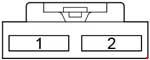
- 10A WIP NO.4 – Cruise control, dynamic cruise control radar, engine control unit
- 10A WIP NO.4 – Cruise control, dynamic cruise control radar, engine control unit
Additional elements Toyota Prius 40 41
Scheme
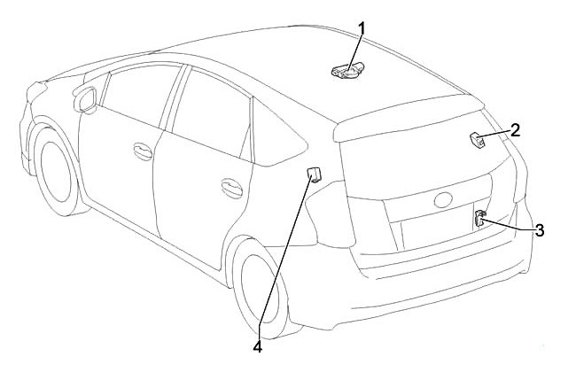
Appointment
- Sliding roof control system ECU
- Door control receiver
- Insert melting unit
- High-voltage battery distribution block assembly
Blocks under the hood Toyota Prius 40 41
Arrangement
General layout of electronic control units under the hood
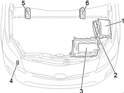
Transcript
- Fuse and relay block
- Engine control unit
- Inverter with converter
- Headlight cleaner relay
- RHD: Brake system control unit
- LHD: Brake system control unit
Fuse and relay block Toyota Prius 40 41
Located in the left side of the engine compartment.
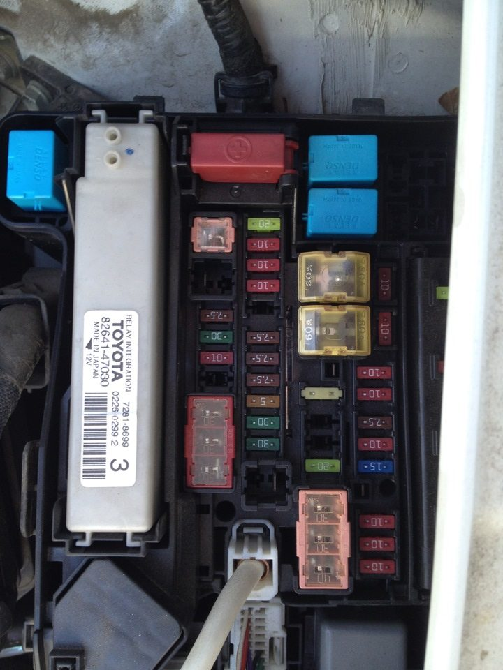
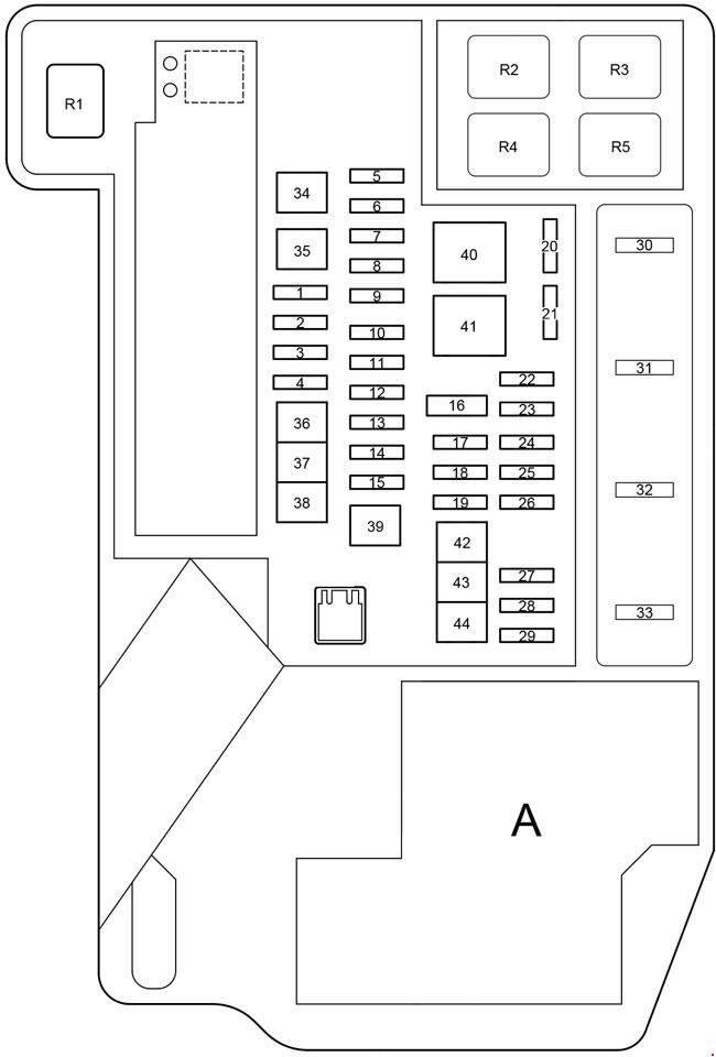
Department A
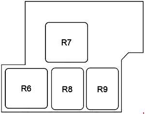
Until October 2012
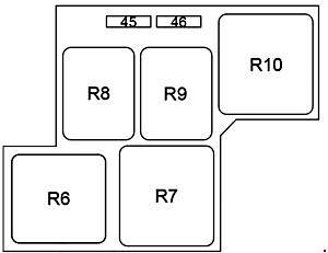
Since October 2012
Fuses
| 1 | ABS MAIN NO.2 7.5 A — Anti-lock braking system |
| 2 | ENG W/P 30 A – Cooling system |
| 3 | S-HORN 10 A – Alarm |
| 4 | AMP 30A – Audio system |
| 5 | ABS MAIN NO.1 20 A — Anti-lock braking system |
| 6 | ETCS 10 A – Multi-point fuel injection system/sequential multi-point fuel injection system |
| 7 | TURN & HAZ 10 A — Turn signals |
| 8 | ECU-B3 10 A – Air conditioning system |
| 9 | MAYDAY 10 A – Telematics system |
| 10 | ECU-B2 7.5 A — Intelligent Entry and Start System |
| 11 | AM2 7.5 A – Power Management System |
| 12 | P CON MAIN 7.5 A – Gearbox selector, gearbox control unit |
| 13 | DC/DC-S 5 A — DC/DC converter and inverter |
| 14 | IGCT 30 A – Fuses: “PCU”, “IGCT NO.2”, “IGCT NO.3” |
| 15 | AMP 30 A – Until October 2014: Audio system |
| HORN 10 A – From October 2014: Signal | |
| 16 | SHORT PIN – Fuses: “ECU-B”, “RAD NO.1”, “DOME” |
| 17 | AMP NO.2 30 A – Audio system, navigation system |
| 18 | DRL 7.5 A – Daytime running lights |
| 19 | H-LP HI MAIN 20 A — High beam headlights, daytime running lights |
| 20 | IGCT NO.3 10 A Cooling system |
| 21 | EFI NO.2 10 A — Multi-point fuel injection system/sequential multi-point fuel injection system |
| 22 | H-LP RH HI 10 A — Right headlight (high beam) |
| 23 | H-LP LH HI 10 A — Left headlight (high beam) |
| 24 | ECU-B 7.5 A — Intelligent entry and start system, multiplex data transmission system, alarm, personal lighting, instruments and indicators |
| 25 | DOME 10 A — Door sill lighting, personal lighting, interior lighting, footwell lighting, individual mirror lighting, interior rearview mirror, electric power steering |
| 26 | RAD NO.1 15 A – Audio system, navigation system |
| 27 | MIR HTR 10 A — Heated exterior rear-view mirrors |
| 28 | IGCT NO.2 10 A — Hybrid system, parking control system, power windows, power supply system, DC/DC converter and inverter, multi-port fuel injection system/sequential multi-port fuel injection system |
| 29 | PCU 10 A — DC-DC converter and inverter |
| 30 | IG2 20 A – Multi-point fuel injection system/sequential multi-point fuel injection system, fuses: “MET”, “IGN”, power supply system |
| 31 | BATT FAN 10 A — Battery cooling fan |
| 32 | EFI MAIN 20 A — Multi-port fuel injection system/sequential multi-port fuel injection system, cooling system, fuse: “EFI NO.2” |
| 33 | – |
| 34 | H-LP CLN 30 A – Headlight cleaner |
| 35 | – |
| 36 | CDS 30 A – Electric cooling fans |
| 37 | RDI 30 A – Electric cooling fans |
| 38 | HTR 50 A – Air conditioning system |
| 39 | P-CON MTR 30 A – Gearbox selector, gearbox control unit |
| 40 | EPS 60 Electric power steering |
| 41 | P/I 1 60 A – Fuses: “IG2”, “EFI MAIN”, “BATT FAN” |
| 42 | ABS MTR 2 30 A — Anti-lock braking system |
| 43 | ABS MTR 2 30 A — Anti-lock braking system |
| 44 | P/I 2 40 A — Parking control system, horn, right headlight (low beam), left headlight (low beam), reversing lights |
| 45 | H-LP LH LO 15 A – Left headlight (low beam) |
| 46 | H-LP RH LO 15 A – Right headlight (low beam) |
Relay
| R1 | Cooling system (ENG W/P) |
| R2 | Cooling system fan (FAN NO.3) |
| R3 | Gearbox selector (P-CON MTR) |
| R4 | Cooling system fan (FAN NO.1) |
| R5 | Anti-theft system (S-HORN) |
| R6 | Dimmer / daytime running lights (DIM/DRL) |
| R7 | Power control unit (IGCT) |
| R8 | Cooling system fan (FAN NO.2) |
| R9 | Daytime running lights (DRL) |
| R10 |
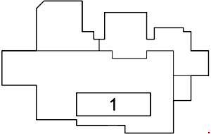
- 125A DC/DC – Integrated relay, “TAIL” relay, “P/POINT” relay, “ACC” relay, “IG1 NO.1” relay, “IG1 NO.2” relay, “IG1 NO.3” relay, switches: “HTR”, “RDI”, “CDS”, “S-HORN”, “ENG W/P”, “ABS MAIN NO.2”, “H-LP CLN”, “FR FOG”, “PWR SEAT FL ”, “OBD”, “STOP”, “RR FOG”, “DBL LOCK”, “PWR SEAT FR”, “DOOR NO.1”, “PSB”, “D FR DOOR”, “P FR DOOR”, “ DOOR RL”, “DOOR RR”, “S/ROOF”