The Volvo FMX is a special truck model manufactured by Swedish company Volvo Trucks, specially designed for tough off-road and construction work. It is a vehicle with increased strength and functionality for tasks that require a strong chassis, excellent traction and the ability to overcome extreme obstacles. Here is some information about the Volvo FMX:
- Durability and design: the Volvo FMX is built to withstand extremely demanding conditions. It has a reinforced chassis, thicker body sheets and other components to provide greater resistance to dynamic loads and tough off-road conditions.
- Application: The FMX is ideal for construction work, transporting heavy loads over difficult terrain, and for infrastructure work where off-road capability is required.
- Powertrain: the Volvo FMX offers advanced powertrain solutions, including high-torque diesel engines that allow it to tackle steep climbs and unpaved roads efficiently.
- Suspension and traction: the FMX features an advanced suspension that improves traction and stability in difficult terrain. Different traction options are available on both axles, depending on the specific requirements of the user.
- Safety: the Volvo FMX is equipped with safety systems such as driver assistance systems, collision avoidance systems and blind spot monitoring to help keep you safe in challenging conditions.
- Cabin and equipment: Volvo FMX cabs are designed with comfort and functionality in construction conditions in mind. They offer ergonomic solutions, advanced multimedia and navigation systems and spacious interiors.
- Sustainable transport: despite its focus on performance in rough terrain, the Volvo FMX also strives for sustainable transport, offering alternative drive options such as gas or hybrid engines.
- Many years of experience: the Volvo FMX is rooted in Volvo Trucks’ long-standing experience of producing vehicles adapted to tough conditions. It continues the tradition of reliable off-road trucks.
In summary, the Volvo FMX is a special truck model designed for tough off-road and construction environments. It offers exceptional durability, off-road capability and advanced technology to perform efficiently in demanding environments.
Checking and replacing fuses
As you know, fuses protect against overloading the electrical system of our cars. When a component stops working, it is most likely that a circuit breaker has tripped or a fuse has blown. Therefore, the fuse responsible for the component should be checked before repair. A blown fuse will be indicated by a melted or completely ruptured tape inside the fuse.
Remember this before replacing the fuse!
- remove the ignition key
- check that everything has been switched off
- always replace fuses with the same amperage.
The vehicle’s fuses are designed to protect the electrical installation circuits from overload and are normally only triggered by a short circuit. Therefore, if a fuse has tripped, always have the cause determined by an authorised Volvo workshop.
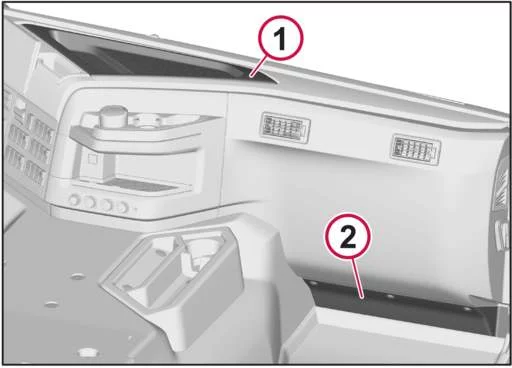
There are two fuse and relay locations in the cab. The fuse and relay panel (1) can be found in the centre of the instrument panel. The body fuses and relays (2) can be found at the front of the passenger seat.In both places, there is a sticker on the cover or under the cover showing the location of the fuses and relays with a description of the functions.
- Fuse and relay control unit
- Body fuses and relays
Fuse and relay control unitThe central unit contains two different types of flat-type fuses. If one and the same fuse requires frequent replacement, the vehicle should be taken to an authorised Volvo workshop for an inspection of the electrical system.
When replacing fuses, always use fuses with the specified current rating. Never use fuses with a higher current rating than the specified current rating.
Switch the electrical system to the “Park” power mode and, if possible, close the faulty circuit before replacing the fuse. Leaving the voltage on may cause the fuse holder to burn out.
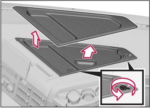
How to access fuses and relaysTo access the fuse and relay control panel in the center of the dashboard, proceed as follows:
- Remove the rubber protection from the glove compartment.
- Turn the locking screws 90 degrees counterclockwise using a coin or similar object.
- Grasp the handle and pull the cover up.
- Remove the cover.
Microwave Oven Fuse
The microwave fuse is located below the fuse and relay panel. The fuse is rated at 50 A.
To access the microwave fuse, follow these steps:
- Disconnect the negative terminal from the batteries.
- Remove the fuse and relay control unit cover.
- Unscrew the screws securing the fuse and relay control unit using a Torx screwdriver.
- Carefully lift and assemble the fuse and relay assembly.
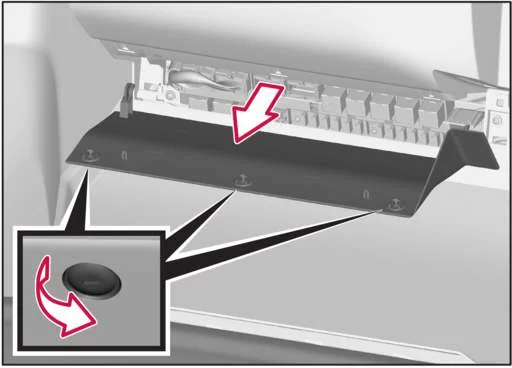
Access to body fuses and relays
To access the body fuses and relays, proceed as follows:
- Turn the locking screws 90 degrees counterclockwise using a coin or similar object.
List of plate fuses
| Number | Amps [A] | Description |
| F 1 | 10A | 12V power outlet |
| F2 | ||
| F3 | 10A | TV/DVD |
| F 4 | ||
| F 5 | ||
| F 6 | 5 A | Body, switch |
| F7 | 30A | Body |
| F8 | 20A | Body |
| F9 | ||
| F10 | 3 A | USB socket |
| F11 | 15A | Additional light for the roof |
| F12 | 15A | Rotating warning light on the roof |
| F13 | 15A | Seat heating / Breathalyzer with ignition lock ALCOLOCK |
| F14 | ||
| F15 | 10A | Roof light board / Parking lights |
| F16 | 10A | Full lighting in the light board on the roof |
| F17 | ||
| F18 | 3 A | – |
| F19 | 15A | BBM control unit , body |
| F20 | 20A | Right side window lifter control unit |
| F21 | 3 A | Control unit, side display |
| F22 | 5 A | Sun visor, left and right side |
| F23 | 3 A | TACHO control unit , tachograph |
| F24 | 5 A | Combined instrument cluster |
| F25 | 3 A | Road toll collection system |
| F26 | ||
| F27 | 10A | Vehicle Control Unit VMCU |
| F28 | 20A | Vehicle Control Unit VMCU |
| F29 | 10A | Heated rear-view mirror, right |
| F30 | 10A | Heated rearview mirror, left |
| F31 | 5 A | DACU Control Unit , Driver Support |
| F32 | 10A | APM Control Unit , Air Dryer |
| F33 | 3 A | Remote control ( Work Remote Control ), charger |
| F34 | 5 A | Safety lock, front cover |
| F35 | 15A | Parking air conditioner fan control unit |
| F36 | 5 A | Camera |
| F37 | 20A | ABS/EBS brake system control unit |
| F38 | 20A | CCM Heating and Air Conditioning Control Unit |
| F39 | 20A | Fuel line heater |
| F40 | 3 A | Tachograph ignition |
| F41 | 15A | EMS engine control unit |
| F42 | 15A | Engine control unit, load |
| F43 | 10A | Fuel Filter Heater |
| F44 | 10A | Engine control unit, load |
| F45 | 30A | Cabin tilt pump |
| F46 | 20A | ABS/EBS system , trailer |
| F47 | ||
| F48 | ||
| F49 | 50A | Power output, body |
| F50 | 30A | Coffee machine |
| F51 | 20A | Windshield wiper motor |
| F52 | 15A | Sunroof Motor |
| F53 | 5 A | Video switcher |
| F54 | ||
| F55 | 3 A | Alarm |
| F56 | 10A | – |
| F57 | 10A | Driver’s cab lighting |
| F58 | 15A | Amplifier |
| F59 | 15A | Voltage converter |
| F60 | 15A | Voltage converter |
| F61 | 20A | Left side window lifter control unit |
| F62 | 5 A | OBD data transfer connector |
| F63 | 10A | CIOM control unit , driver’s cab |
| F64 | 15A | 24V power outlet |
| F65 | 15A | 24V power outlet |
| F66 | 3 A | Dynafleet/Telematic |
| F67 | 15A | Lighter |
| F68 | 15A | Vehicle Control Unit VMCU |
| F69 | 15A | Parking heater |
| F70 | 20A | TECU |
| F71 | 15A | Headlight washers |
| F72 | 5 A | |
| F73 | 30A | Body function active in driving mode |
| F74 | 20A | Body function active in driving mode |
| F75 | 10A | Refrigerator |
| F76 | 15A | – |
| F77 | ||
| F78 | ||
| F79 | ||
| F80 | 3 A | LECM Rear Control Panel |
| F81 | 5 A | SRS airbag |
| F82 | 3 A | ERA GLONASS Control Unit |
| F83 | ||
| F84 | ||
| F85 | 3 A | FMS power supply , driving |
| F86 | ||
| F87 | ||
| F88 | 5 A | Breathalyzer with ignition lock ALCOLOCK |
| F89 | ||
| F90 | 15A | Electrically adjustable seat |
| F91 | 10A | FMS Power Connector |
| Number | Relay type | Description |
| K01 | ISO micro 10A | – |
| K02 | ISO micro 10A | Refrigerator |
| K03 | ISO mini 20A | Roof vent motor 2 |
| K04 | ISO mini 20A | Roof vent motor 1 |
| K05 | ISO mini 20A | Windshield wiper motor on/off |
| K06 | ISO mini 20A | Windshield wiper motor high/low speed |
| K07 | ISO power 40 A | Body function, fuses |
| K08 | ISO power 40 A | Accessories |
| K09 | ISO micro 10A | Seat heating, breathalyzer with ALCOLOCK ignition lock |
| K10 | ISO mini 20A | Additional light for the roof |
| K11 | ISO power 40 A | Power amplifier, voltage converter, cabin lighting |
| K12 | ISO micro 10A | Light board on the roof |
| K13 | ISO mini 20A | Rotating warning light on the roof |
| K14 | ISO power 40 A | 24V power socket, cigarette lighter, breathalyzer with ALCOLOCK ignition lock |
| K15 | ISO micro 10A | Full lighting in the light board on the roof |
| K16 | ISO mini 20A | Headlight washers |
| K17 | ISO mini 20A | TECU |
| K18 | ISO micro 10A | – |
| K19 | ISO mini 20A | – |
| K20 | ISO power 40 A | Body function ignition, active in driving mode |
| K21 | ISO micro 10A | Electrically heated rear-view mirrors |
| K22 | ISO mini 20A | Ignition |
| K23 | ISO power 40 A | – |
| K24 | ISO micro 10A | Electrically adjustable seat |
| K25 | ISO micro 10A | – |
| K26 | ISO micro 10A | Camera |
| K27 | ISO power 40 A | EMS engine control unit |
| K28 | ISO power 40 A | Cabin tilt pump |
The main fuses are located in the main fuse box, which is located inside the battery box on the frame. Under normal conditions, the fuses will last the lifetime of the vehicle. If a fuse blows, the vehicle should be taken to an authorised Volvo workshop for an inspection of the electrical system.
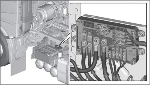
The fuses are screwed into the fuse box using nuts with a captive spring washer. It is important that the nuts are tightened to the correct torque, see table. Too little torque can cause heating. Too much torque can cause deformation and cracks.
| Size | Tightening torques |
| M5 | 4.5Nm ±5% |
| M8 | 20.0Nm ±5% |
| M10 | 40.0Nm ±5% |
Use the correct tightening torque.When replacing fuses, always use fuses with the specified current rating. Never use fuses with a higher current rating than the specified current rating.
| Number | Amps [A] | Description |
| 1 | 200A | Body function |
| 2 | 100A | FRC Driver’s cab, fuse and relay control unit |
| 3 | 30A | Front Chassis Control Unit FCIOM |
| 4 | 30A | Central chassis control unit CCIOM |
| 5 | 30A | Rear Chassis Control Unit RCIOM |
| 6 | 30A | Front Chassis Control Unit FCIOM |
| 7 | 30A | Central chassis control unit CCIOM |
| 8 | 30A | Rear Chassis Control Unit RCIOM |
| 9 | 30A | FAS front axle control |
| 10 | 40A | PCCU Parking air conditioner |
| 11 | 23 A | ACM Exhaust Gas Treatment Control Module |
| 12 | 23 A | Additional axis control |
Battery System Fuses The battery system fuses are located on the left side of the starter battery box.
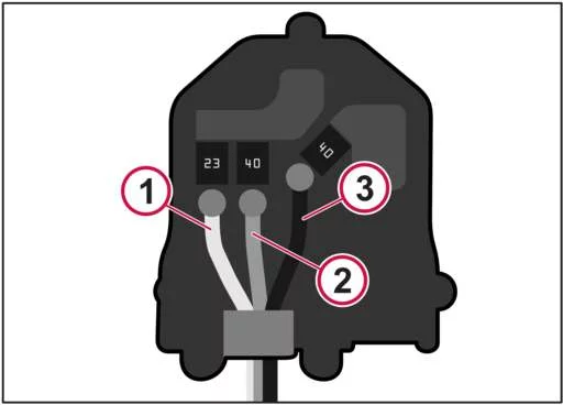
Battery system fuse box
| Number | Amps [A] | Description |
| F1 | 23 A | Built-in equalizer charger and vehicle batteries |
| F2 | 40A | Control unit for battery management and vehicle batteries |
| F3 | 40A | Control unit for battery management and starter batteries |