Scania 5 6 series , so many call a group of trucks produced since 2005 to the present time in two generations, which includes such series as Scania P, G, R, T and many others. In our material we will show a description of the fuses and relays Scania 5 / 6 series with a block diagram and a photo example of its execution. We will highlight the fuse responsible for the cigarette lighter.
Fuse and relay box
The main block with fuses and relays is located in the instrument panel, on the passenger side behind the protective cover.
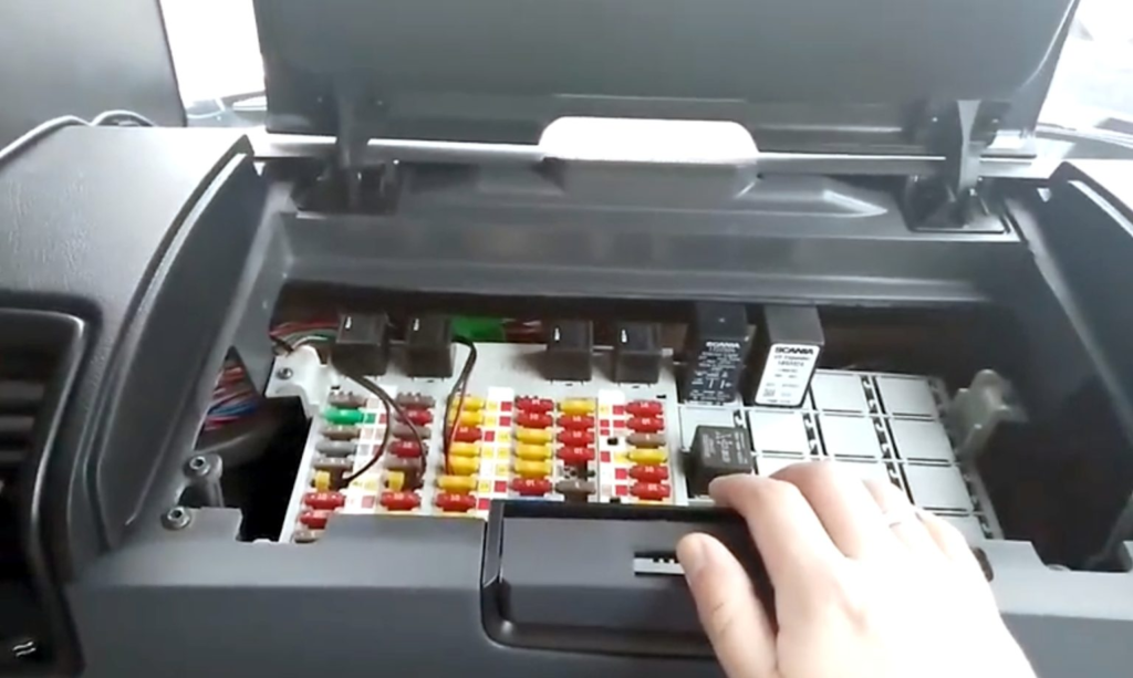
The execution of the unit and the purpose of the elements may differ from that shown. Check the purpose with your diagram on the back of the cover.
Fuse diagram
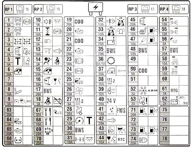
Transcript
| 1 | 5A ECU, ABS/EBS trailer |
| 2 | 30A Trailer Valves |
| 3 | 5A PT01, PT02, GMS, BWE, ZTE, start-stop |
| 4 | 2A Mirror adjustment, reversing alarm |
| 5 | 5A Interior lighting (exclusive), lane departure warning |
| 6/1 | 20A Left window lifter |
| 6/2 | 30A Glass lift, left side, double cabin |
| 7 | 20A Additional Air Conditioning, Double Cabin |
| 8 | 10A Cigarette Lighter |
| 9 | 5A Cruise control/AICC |
| 10 | 5A ACC/MCC, tachograph |
| 11 | 10A Differential Locks, ABS 6-channel |
| 12 | 5A Daytime Running Lights, Additional Light Switch |
| 13 | 10A Additional Axle Lift Mechanism, EEC |
| 14 | 5A Airbag, seat belt pretensioner |
| 15/1 | 20A Right window lifter |
| 15/2 | 30A Glass lift, right side, double cabin |
| 16 | 10A Breathalyzer (alcolock), voltage from terminal 15 |
| 17 | 20A Body |
| 18 | 5A Battery Disconnect Switch |
| 19 | 20A Coordinator |
| 20 | 20A Power Supply, EMS Control Unit |
| 21 | 10A Ignition switch |
| 22 | 20A Power Supply, EMS Control Unit |
| 23 | 10A Inverter |
| 24 | 20A ABS/EBS |
| 25 | 10A Power Supply, ELC Control Unit |
| 26 | 20A Cabin Fan |
| 27 | 5A CT |
| 28 | 20A Sunroof |
| 29 | 10A Instrument cluster, tachograph |
| 30 | 30A Body |
| 31 | 10A AWD Control Unit, Interior Lighting |
| 32 | 10A SDP3 (diagnostics) |
| 33 | 10A Toll Registration Preparation Kit (for Switzerland), Flashing Beacon |
| 34 | 20A 24V/12V Voltage Converter, 12V Electrical Socket |
| 35 | 20A Additional Equipment Electrical System |
| 36/1 | 20A OPC |
| 36/2 | 10A Allison |
| 37 | 10A Central locking |
| 38 | 15A Additional heater (ATA, WTA) |
| 39 | 10A Reverse Light Switch Panel |
| 40 | 20A 24V Electrical Socket |
| 41 | 10A APS Control Unit, Electrical Auxiliary Equipment System |
| 42 | 20A Electric Cabin Tilt Mechanism |
| 43 | 10A Refrigerator |
| 44 | 10A Breathalyzer (Alcolock) |
| 45 | 20A Rearview mirror heating, windshield heating |
| 46 | 10A Seat heating, oil cooling fan |
| 47 | 10A Engine timer, fuel filter heater, water separator suction filter heater |
| 48 | 10A Body |
| 49 | 30A RES, MGU |
| 50 | 5A Yellow and green warning bus |
| 51 | 30A Coolant pump |
| 52 | 2A Alarm |
| 53 | 2A Sunroof Open Warning |
| 54 | 10A Side marker light, left side |
| 55 | 10A Side marker light, starboard side |
| 56 | 5A Background lighting, side lights |
| 57 | 20A Body |
| 58 | 10A Trailer, left side |
| 59 | 10A Trailer, right side |
| 60 | 20A Working Light |
| 61 | 2A FMS, Bodywork equipment |
| 62 | 2A 24V/12V Voltage Converter Remote Immobilizer |
| 63 | 10A Driver Warning Block, Front Video Camera |
| 64 | 5A SMS |
| 65 | 20A Variable Geometry Turbocharger |
| 66 | 10A Power Supply, TPM Control Unit |
| 67 | 30A Kitchen module, cabin lifting system |
| 68 | 10A TV power supply voltage |
| 69 | 20A Trailer Axle Lock/Oil Cooling Fan |
| 70 | 10A Radar |
| 71 | 20A Fuel Heater, Fuel Cooler System |
| 72 | 10A Electric Throttle Actuator |
| 73 | 20A Fuel Heater, Fuel Cooler System |
| 74 | 10A Headlight Cleaning |
| 75 | 30A Coolant pump |
| 76 | 5A DC to DC Converter Battery Pack |
| 77 | 5A Battery Block |
| 78 | 15A Coolant pump, gearbox |
Fuse number 8 for 10A is responsible for the cigarette lighter.
Relay department diagram
Relays RР1 – RР4 (on the upper diagram)
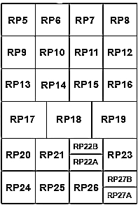
Description of the relay
| RP1 | Voltage supply from terminal 15 |
| RP2 | Voltage supply from terminal 15 |
| RP3 | controlled by VIS |
| RP4 | Power supply from terminal 58, controlled by VIS |
| RP5 | Interior lighting |
| RP6 | Additional bridge lifting mechanism |
| RP7 | Stop signals |
| RP8 | Reversing light |
| RP9 | Resistor block for cars with cruise control without buttons of this system on the steering wheel |
| RP10 | ECU for FMS preparation |
| RP11 | ECU for FMS preparation |
| RP12 | AC Relay (Crew Cab) |
| RP13 | Safety switch |
| RP18 | Additional relay for power supply from terminal 15 for type S vehicles |
| RP19 | Electronic Cabin Lift System Relay |
| RP20 | Tail lift and kitchen equipment |
| RP23 | Additional light |
| RP24 | Additional light |
| RP25 | Additional light |