We consider fuses and relays in the Renault Megane 3rd generation car – 2008, 2009, 2010, 2011, 2012, 2013, 2014, 2015, 2016 years of release with petrol and diesel engines.
Fuses and relays in the Renault Megane 3 cabin
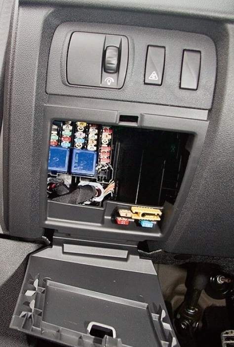
The main mounting block in the vehicle interior is located on the driver’s side at the bottom of the control panel.
Renault Megane 3 Interior Fuse Box Diagram
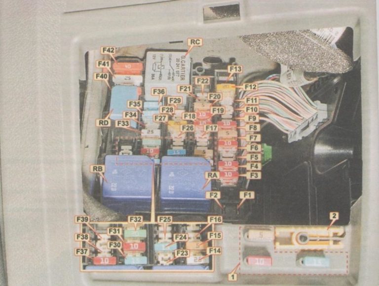
Description
| F1 | reserve |
| F2 | reserve |
| F3 | 10A cigarette lighter fuse Renault Megane 3 |
| F4 | 10A rear socket |
| F5 | 10A socket in the luggage compartment |
| F6 | 10A audio system |
| F7 | 5A heated exterior mirrors |
| F8 | 10A windshield washer, door open indicator |
| F9 | 30A Automatic Parking Brake |
| F10 | 10A Instrument Panel Shield |
| F11 | 25A electric seat, steering column switches |
| F12 | 20A Electric heated passenger seat |
| F13 | reserve |
| F14 | 25A electric window lifter front passenger door |
| F15 | 5A Brake Light Switch, Brake Pedal Position Sensor, ABS/ESP Control Unit |
| F16 | 25A electric window lifter right rear door |
| F17 | 25A electric window lift left rear door |
| F18 | 10A glove compartment light, left luggage compartment light, door lights, sun visor mirror lights, rain sensor |
| F19 | 10A clock, outside temperature indicator, seat belt reminder, audio system connector |
| F20 | 5A climate control unit |
| F21 | 3A Sun Visor Mirror Lights |
| F22 | 3A interior lights, rain and light sensor |
| F23 | 20A trailer socket |
| F24 | 15A UCHBS |
| F25 | 3A Interior Rearview Mirror |
| F26 | 10A navigation system, CD changer, audio system |
| F27 | 20A audio system, parking brake control unit |
| F28 | reserve |
| F29 | reserve |
| F30 | 15A UCHBS, direction indicators |
| F31 | 10A UCHBS |
| F32 | 30A electric window lift driver’s door |
| F33 | 25A UCHBS, central locking |
| F34 | 30A Passenger Door Multiplex Network ECU |
| F35 | 15A clock, outside temperature indicator, phone display |
| F36 | 15A diagnostic connector, horn relay, alarm control unit, siren |
| F37 | 10A brake lights, electrical equipment control unit |
| F38 | 30A Automatic Parking Brake |
| F39 | 30A Convertible Roof ECU |
| F40 | 40A air conditioning fan |
| F41 | 25A sunroof electric drive |
| F42 | 40A rear window heating |
- RA 70A — power relay (+battery) with shutdown delay (without power shutdown at startup)
- RB 70A — power relay (+battery) with shutdown delay (with power shutdown at startup)
- RC 40C — Rear Window Defogger Relay
- RD 20A – Horn Relay
Fuses and relays under the hood of Renault Megane 3
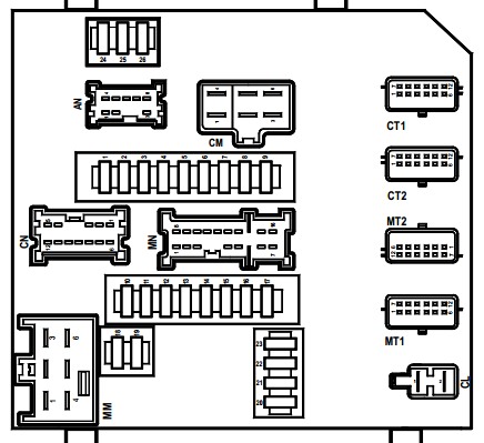
The main unit in the engine compartment is considered to be the protection and switching unit, located on the left side near the pillar and the wing of the car.
Fuse and relay box diagram under the hood of Renault Megane 3
Description
- 10A — Side light (right headlight, right rear light, headlights), license plate lights, cigarette lighter light, electric window switch light, audio system, navigation system control unit, multimedia system keyboard
- 10A – Side light (left headlight, left rear light), left light on the luggage compartment door
- 15A – Headlight washer pump
- 20A – Fog lights
- 10A – High beam (left headlight)
- 10A – High beam (right headlight)
- 15A — Diagnostic connector, rear window heating relay, automatic transmission mode selector, electric headlight corrector, gas discharge lamp control unit, additional heater control unit, speed limiter, automatic parking brake, automatic parking system control unit, dimming mirror in the passenger compartment
- 30A — ABS, ESP control unit
- 30A – Front wiper
- 10A – Airbag control unit
- 20A – Not used
- 7.5A – Gearbox ECU
- 25A – Engine Management System
- 15A – Oxygen concentration sensors – heating
- 20A — Gearbox ECU
- 5A – Brake lights, electrical equipment control unit, electric power steering
- 10A — Automatic transmission mode sensor, electric headlight corrector, reverse light relay
- 15A – Electrical equipment control unit
- 30A – Starter
- — Not used
- 20A — Fuel module, ignition coils, ECU of the liquefied gas fuel system
- 10A – Air conditioning compressor electromagnetic clutch
- 5A — Injection system control unit
- 20A – Low beam (left headlight), electric corrector
- 20A – Low beam (right headlight), electric corrector
- — Not used
Important! Fuses 24, 25 and 26 on the protection unit may not be removable.
Block #2 in the engine compartment of Renault Megane 3
The mounting block is located under the protection and switching block.
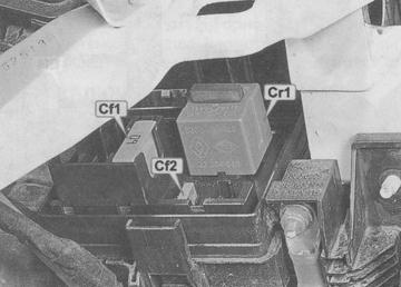
Fuse and relay box diagram under the hood of Renault Megane 3
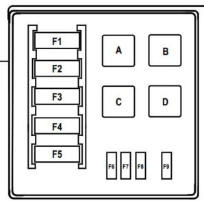
Description
- A – Not used
- B — Fuel heater relay
- C — Reverse light relay
- D — Not used
- F1 — 80A immersion heater control unit
- F2 — 70A pre-heating unit
- F3 – Not used
- F4 — 80A immersion heater control unit
- F5 — 60A / 40A electric fan relay
- F6 — 20A Fuel heater
- F7 – Not used
- F8 — 30A electric fan relay
- F9 – Not used
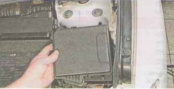
Blocks near the battery
There are 2 additional blocks located near the battery.
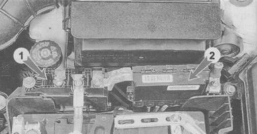
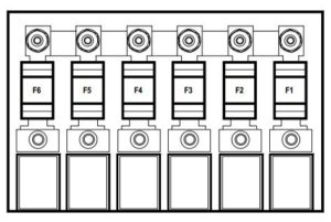
Battery disconnect unit diagram (in Fig. 1)
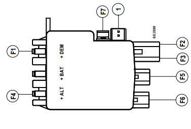
Description
- F1 — 190A Starter
- F2 — 50A fuse and relay box in the passenger compartment
- F3 — 80A fuse and relay box (control and switching unit) in engine compartment 1, fuse and relay box in the passenger compartment
- F4 – 300A / 190A Engine Compartment Fuse and Relay Box 2 / Generator
- F5 — 80A Electric Power Steering
- F6 — 35A Electronic Engine Control Unit (ECU) / Fuse and Relay Box (Control and Switching Unit) in the Engine Compartment 1
- F7 — 5A fuse and relay box (control and switching unit) in the engine compartment 1
Schematic diagram of the high power fuse block (in Fig. 2)
Description
- 70A – additional interior heater
- 80A – fuse and relay box in the passenger compartment
- 80A – fuse and relay box in the passenger compartment
- 80A – fuse and relay box (control and switching unit) in engine compartment 1, fuse and relay box in the passenger compartment
- 30A – additional heater
- 50A — ABS ECU with ESP
Important! The engine cooling system electric fan relay may be located next to the electric fan.