Mitsubishi L200 4th generation pickup truck was produced in 2005, 2006, 2007, 2008, 2009, 2009, 2010, 2011, 2012, 2013, 2014, 2015. In some countries it is known under the name Mitsubishi Triton. In our material you will find a description of fuses and relays Mitsubishi l200 4th generation with block diagrams and their locations. Let’s highlight the cigarette lighter fuse.
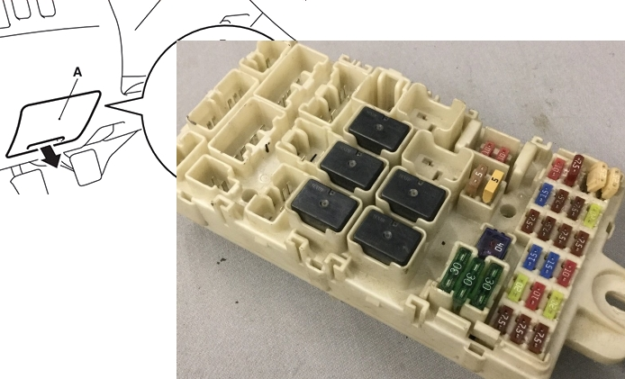
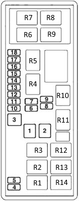
The unit in the passenger compartment
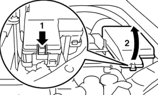
Located at the bottom of the dashboard on the driver’s side behind the protective cover.
Location of the unit
Description of fuses
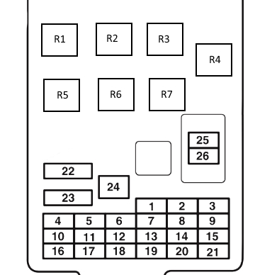
| 1 | 7.5A Side lights (left) |
| 2 | 15A Cigarette Lighter |
| 3 | 10A Ignition Coil |
| 4 | 7.5A Starter |
| 5 | 20A Sunroof |
| 6 | 15A Socket, Accessory Socket |
| 7 | 7.5A Parking lights (right), A/C control unit, ASC OFF switch, Blind spot warning switch, Combination meter, Driving mode switch, Electric parking brake switch |
| 8 | 7.5A Exterior mirrors |
| 9 | 7.5A Engine ECU and Fuel Pump Relay |
| 10 | 7.5A Control Unit |
| 11 | 10A Rear Fog Light |
| 12 | 15A Central lock, Diagnostic socket |
| 13 | 10A Air conditioner ECU, Camera ECU, Central room light, Column switch, Combination meter, Door light, Electric parking brake switch, Front room light, Gateway interface control unit, Key reminder switch (ILL), KOS and OSS ECU, Light control sensor, Luggage compartment light, Multi display, Radio/CD player and Rear display |
| 14 | 15A Rear Window Wiper |
| 15 | 7.5A Instrument cluster, blind spot warning sensor, clearance warning control unit, steering column switch |
| 16 | 7.5A A/C Compressor Relay, A/C Condenser Fan Relay, Fan Relay, Heater Controller, Rear Fan Relay, Rear Cooler Control Panel, Rear Fan Switch and Rear Defogger Relay |
| 17 | 20A Seat heating |
| 18 | 10A Accessory Power Supply, Heater Controller Assembly |
| 19 | 7.5A Heated exterior mirrors |
| 20 | 20A Windshield wipers |
| 21 | 7.5A Reversing lights, Automatic transmission control unit, ETACS control unit, Multi-function display, Radio/CD player, Rear combination light (rear), Rear view mirror assembly and SRS control unit |
| 22 | 30A Rear Window Defogger, Fuse #19, Glass Antenna Throttle Coil & Rear Window Defogger |
| 23 | 30A Heater Fan Motor Relay |
| 24 | 40A Power Seats |
| 25 | 10A Audio System, Accessory Socket Relay, ETACS-ECU, Multi-Display, Radio/CD Player and Rear Display |
| 26 | 15A Fuse #13 and ETACS-ECU |
Fuses numbers 2 and 6, as well as relay number 2, are responsible for the operation of the cigarette lighter and power sockets.
Relay designation
- R1 — Seat heating relay
- R2 — Power supply relay for additional equipment sockets
- R3 — Rear fog light relay
- R4 — Fuel pump relay
- R5 — Fan relay
- R6 — Rear window heating relay
- R7 — Reserve
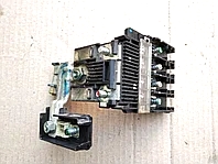
Blocks under the hood
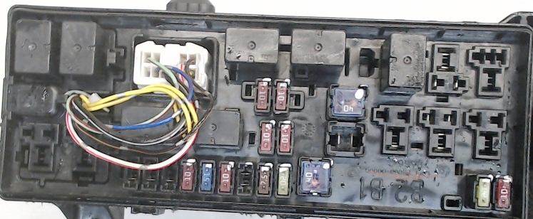
Main block
Located on the left side of the engine compartment, near the battery.
Purpose of fuses
| 1 | Reserve |
| 2 | 40A Electric window drive system |
| 3 | 40A Ignition Switch |
| 4 | 10A Air Conditioning Compressor |
| 5 | 20A Condenser Fan Motor |
| 6 | 10A High beam headlight (left) |
| 7 | 10A High beam headlight (right) |
| 8 | 10A Low beam headlight (left) |
| 9 | 10A Low beam headlight (right) |
| 10 | 20A Engine Control |
| 11 | 7.5A Alternator |
| 12 | 15A Brake lights |
| 13 | 10A Signal |
| 14 | 20A Automatic transmission |
| 15 | 10A Hazard warning light |
| 16 | 15A Fuel pump |
| 17 | 15A Front fog lights |
| 18 | 20A Audio Amplifier |
Decoding the relay
| R1 | Fog light relay |
| R2 | Condenser Fan Electric Motor Relay |
| R3 | Reserve |
| R4 | Starter |
| R5 | Horn relay |
| R6 | Fuel supply line heater |
| R7 | Automatic transmission |
| R8 | Main relay of the injection system |
| R9 | Electric mag. clutch of air conditioner compressor |
| R10 | Low beam headlights |
| R11 | High beam headlights |
| R12 | Relay for electric drives of window lifters |
| R13 | Headlight washer |
| R14 | Reserve |
Additional blocks
Depending on the year of manufacture and the level of equipment, additional units may be located in the engine compartment of the Mitsubishi L200.
Block near the battery
Next to the battery there is a fuse block made in the form of fusible links.
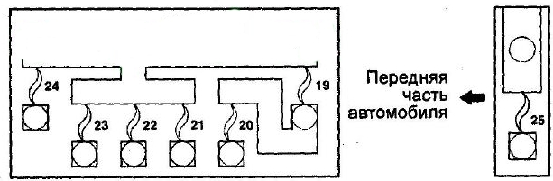
Description
| 19 | 120A Generator |
| 20 | 100A Fuses (No. 4, 5) located in the mounting block in the engine compartment; fuses (No. 5, 6, 11, 12, 17, 18, 22, 23, 26) and a fusible link (No. 24) located in the mounting block in the passenger compartment |
| 21 | 30A Control unit (ABS or ASC) |
| 22 | 50A ABS Malfunction Relay; ASC Control Unit |
| 23 | 120A Fuse links (No. 2, 3) and fuses (No. 10, 11, 12, 13, 14, 15, 16, 17, 18) located in the mounting block in the engine compartment |
| 26 | 50A Fuel line heater; coolant heater |
Block near the right drain
The following relays can be mounted in it: ABS Pump Motor Relay and ABS Malfunction Relay
Block next to the engine
It is installed mainly on diesel models. Here are the relays responsible for heating the additional electric heater.