Honda Accord 10 generation was produced in 2018, 2019, 2020, 2021, 2022, 2023. The Honda Accord Hybrid version gained the greatest popularity. In our material you will find information with a description of the fuses and relays of the Honda Accord 10 with block diagrams, their locations and photo examples of execution. Let’s highlight the cigarette lighter fuse.

The purpose of fuses and relays may differ from those presented and depends on the year of manufacture, region of delivery and equipment level of your vehicle. Compare the information with your diagrams.
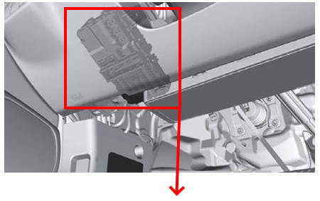
Block in the cabin
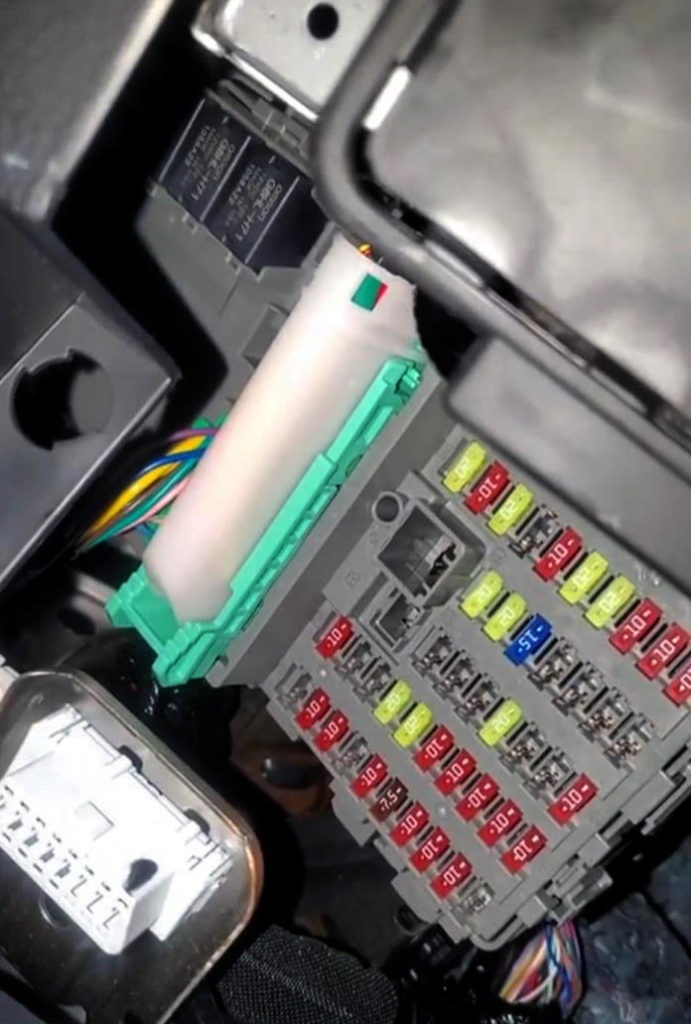
In the cabin, the fuse box is located at the bottom of the instrument panel on the driver’s side.
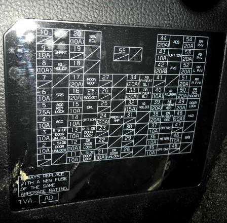
Example of a diagram with notation
Scheme
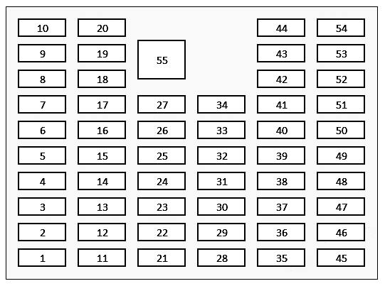
Description
| 1 | – |
| 2 | 10A Door opening left side |
| 3 | 10A Door opening on the right |
| 4 | 10A Power from the ignition switch |
| 5 | 7.5A Power lock from ignition switch |
| 6 | 10A Airbags |
| 7 | – |
| 8 | 10A Engine control (IG HOLD 2) |
| 9 | 10A SMART |
| 10 | – |
| 11 | 10A Door closing left side |
| 12 | 10A Closing the driver’s door |
| 13 | 10A Door opening on the right |
| 14 | 10A Reserve |
| 15 | 10A Daytime running lights |
| 16 | 20A Power sockets (cigarette lighter) |
| 17 | 20A Luke |
| 18 | – |
| 19 | – |
| 20 | 10A SBW Electronic Control Unit |
| 21 | 10A Opening the driver’s door |
| 22 | – |
| 23 | – |
| 24 | 20A Amplifier |
| 25 | – |
| 26 | – |
| 27 | – |
| 28 | – |
| 29 | – |
| 30 | – |
| 31 | – |
| 32 | 15A Engine control (IG HOLD 3) |
| 33 | 20A Driver’s seat adjustment (power supply) |
| 34 | 20A Passenger seat adjustment (power supply) |
| 35 | 10A Reserve |
| 36 | 10A Devices |
| 37 | 10A Reserve |
| 38 | 20A Driver’s seat adjustment (power supply) |
| 39 | 20A Passenger seat adjustment (power supply) |
| 40 | 10A Driver’s seat adjustment (power supply) (transverse) |
| 41 | – |
| 42 | 20A AVS |
| 43 | 10A Reserve |
| 44 | 20А ADS |
| 45 | – |
| 46 | 10A SRS System |
| 47 | – |
| 48 | 10A SKIN |
| 49 | 20A Door closing |
| 50 | 20A Front sockets (cigarette lighter) |
| 51 | 20A Electric window regulator rear right |
| 52 | 20A Electric window regulator rear left |
| 53 | 20A Front passenger power window |
| 54 | 20A Driver’s electric window regulator |
| 55 | – |
The cigarette lighters are controlled by fuses 50 and 16 at 20A. Also, 2 relays located in the upper part of this unit are responsible for the operation of the cigarette lighters (sockets).
Block under the hood
Under the hood, in the engine compartment on the left, is the main fuse and relay block. To access it, you must remove the protective cover.
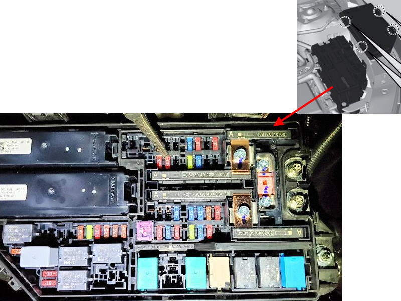
Photo example of a circuit from the block cover
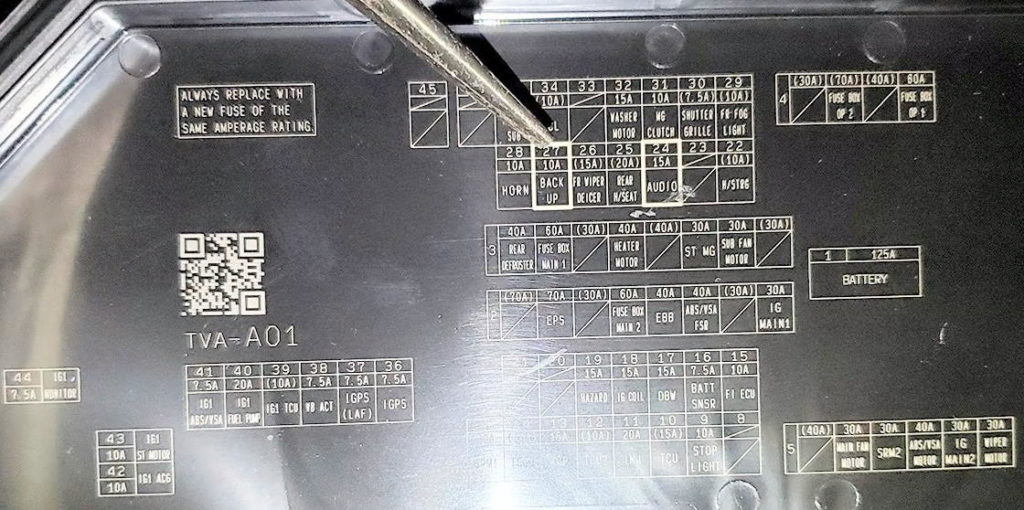
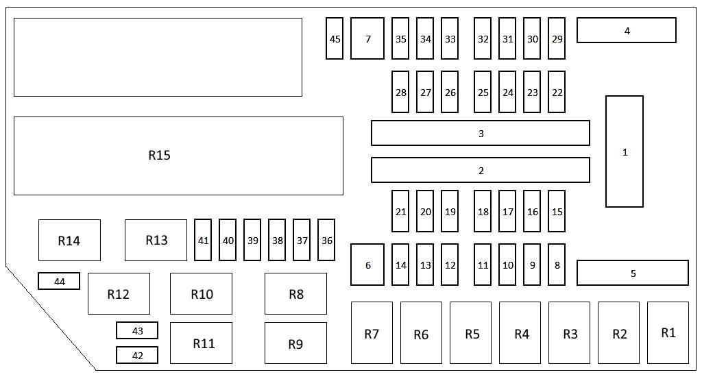
Transcript
| 1 | 125A Battery |
| 2 | 70A – |
| 2 | 70А EPS |
| 2 | 30A – |
| 2 | 60A Main fuse block 2 |
| 2 | 40A EBB |
| 2 | 40A ABS/VSA FSR |
| 2 | – |
| 2 | 30A IG Main |
| 3 | 40A Rear heater |
| 3 | 60A Main fuse block 1 |
| 3 | 30A – |
| 3 | 40A Heater motor |
| 3 | 40A – |
| 3 | 30А ST MG |
| 3 | 30A Auxiliary fan motor |
| 3 | 30A |
| 4 | 30A |
| 4 | 70A Fuse Block 2 (optional) |
| 4 | 40A – |
| 4 | 60A Fuse Block 1 (optional) |
| 5 | 40A – |
| 5 | 30A Main fan motor |
| 5 | 30А SPM2 |
| 5 | 40A ABS/VSA motor |
| 5 | 30A IG Main 2 |
| 5 | 30A Wiper motor |
| 6 | 30A SRM1 |
| 7 | – |
| 8 | – |
| 9 | 10A Stop signal |
| 10 | 15A TCU (optional) |
| 11 | 20A Injector (fuel injection) |
| 12 | 10A TCU2 (option) |
| 13 | 15А IGP |
| 14 | 10A TCU3 (option) |
| 15 | 10A Electronic control unit FI |
| 16 | 7.5A BATT SNSR |
| 17 | 15A DBW |
| 18 | 15A Ignition coil |
| 19 | 15A Emergency alarm |
| 20 | – |
| 21 | – |
| 22 | 10A Heated steering wheel H/STRG (optional) |
| 23 | – |
| 24 | A15 AUDIO |
| 25 | 20A Rear seat heating (option) |
| 26 | 15A Heated front wiper (option) |
| 27 | 10A Reverse light |
| 28 | 10A Signal |
| 29 | 10A Front fog lights (option) |
| 30 | 7.5 Front closable blinds (optional) |
| 31 | 10A Clutch |
| 32 | 15A Washer motor (washer) |
| 33 | – |
| 34 | 10A |
| 35 | 7.5A Audio SUB (optional) |
| 36 | 7.5А GPS |
| 37 | 7,5А IGPS (LAF) |
| 38 | 7,5A VB ACT |
| 39 | 10A IG1 TCU (optional) |
| 40 | 20A IG1 Fuel pump |
| 41 | 7.5A IG1 ABS/VSA |
| 42 | 10А IG1 ACG |
| 43 | 10A IG1 Starter Motor |
| 44 | 10A IG1 Monitor |
| 45 | – |
| Relay | |
| R1 | PGM-FI Main Relay 2 (4p) |
| R2 | Horn relay |
| R3 | Fog light relay |
| R4 | Air conditioner compressor clutch relay |
| R5 | Electric fan relay |
| R6 | – |
| R7 | Rear window heater relay |
| R8 | Rear seat heating relay |
| R9 | Steering wheel heating relay |
| R10 | Radiator Fun Relay |
| R11 | Air conditioner condenser fan relay |
| R12 | Fan control relay |
| R13 | Wiper zone heater relay |
| R14 | Injector relay |
| R15 | Relay board |