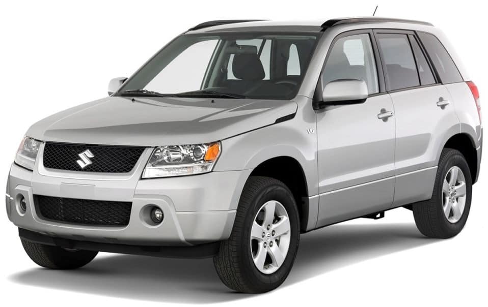
The Suzuki Grand Vitara represents the third generation of the Vitara range. In this publication, you will find a description of the fuse and relay boxes of the Suzuki Grand Vitara 2005, 2006, 2007, 2008, 2009, 2010, 2011, 2012, 2013 and 2014. We will show you where these boxes are located, their diagrams and photo examples. Let’s highlight the fuse responsible for the cigarette lighter.
Engine compartment
Main fuse box
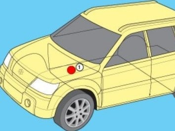
It is located on the left side, near the counter.
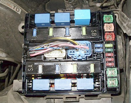
The current assignment of the fuses and relays is shown in the form of a diagram on the back of the cover.
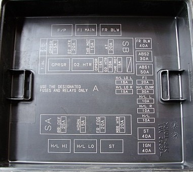
Scheme
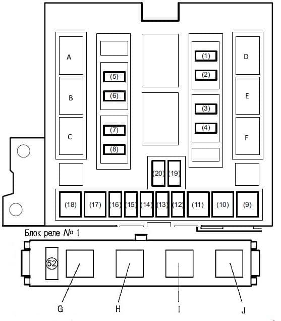
Marking
| 1 | 15A Air Conditioner Electromagnetic Clutch |
| 2 | Oxygen sensor heater 20A |
| 3 | Electric choke 15A |
| 4 | Automatic transmission 20A |
| 5 | 25A Heated rear window |
| 6 | 15A Audible signal |
| 7 | 20A Fog lights |
| 8 | 20A Heated mirrors |
| 19 | 15A Left headlight (low beam), left gas discharge headlight, low beam relay |
| 20 | 15A Right headlight (low beam), right gas discharge headlight, low beam relay |
| 9 | 40A heater fan |
| 10 | 30A ABS control unit 2, ESP control unit |
| 11 | 50A ABS control unit 1, ESP control unit |
| 12 | Main relay 20A |
| 13 | 30A Headlight washer pump |
| 16 | 10A Left headlight (high beam) |
| 15 | 10A Right headlight (high beam) |
| 16 | 10A High beam relay, low beam relay |
| 17 | 40A Starter ST |
| 18 | 40A Ignition switch IGN |
Relay
| A | Headlight high beam relay |
| B | Headlight low beam relay |
| C | Starter relay |
| D | Fuel pump relay |
| E | the main thing |
| F | Heater fan motor |
| G | Electric throttle |
| H | Cooling system fan motor No. 1, 2, 3 |
| I | |
| J | |
| K | Brake light relay |
Additional relay box
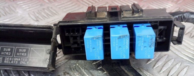
Additional box
It is located near the battery and consists of power fuses.
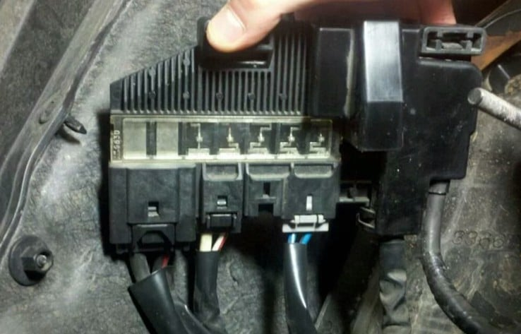
Scheme
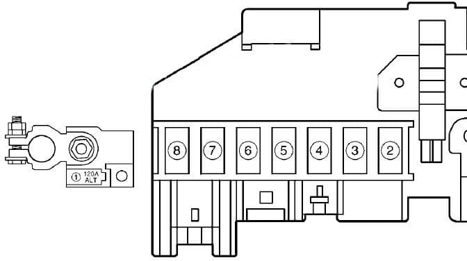
Appointment
| 1 | 120/80A All circuits, battery, fuse block #1 |
| 2 | 30 / 40Ð Cooling system fan motor relay #2 and #1 |
| 3 | |
| 4 | 4WD control unit 40A |
| 5 | 50A Ignition switch |
| 6 | 60A Fuse block No. 2, low beam relay, mounting block |
| 7 | Integrated relay block No. 1, integrated relay block No. 2, fuse block No. 2 |
| 8 | Fuse block #2 |
Passenger lounge
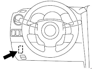
It is installed on the left pillar, on the driver’s side, under the dashboard.
Photo
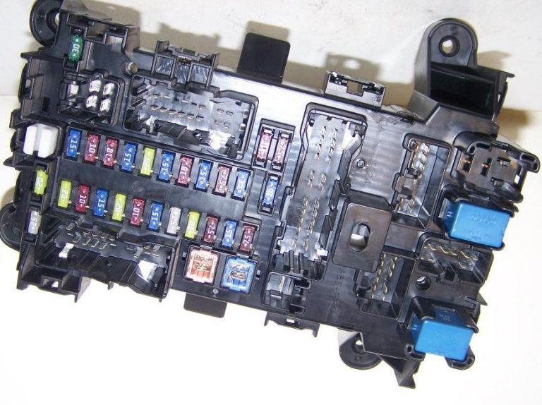
The circuit diagram will be printed on the protective cover of the unit.
Scheme
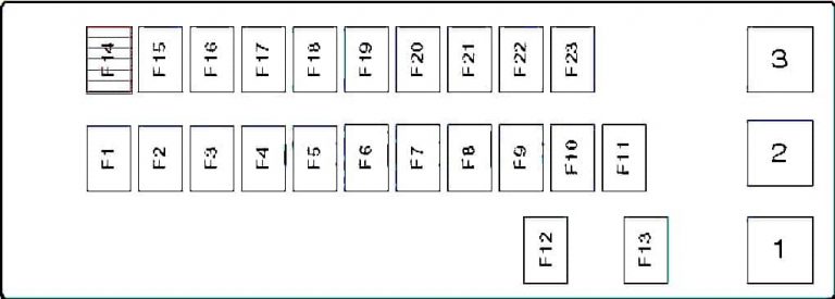
Appointment
| 1 | Trunk door relay |
| 2 | Auxiliary ignition circuit relay |
| 3 | Transmission selector lock relay (range “P”) |
| F1 | (20A) Generator, ignition coils, engine ECU |
| F2 | (10A) ECM, instrument panel |
| F3 | (15A) ECM, display, audio system |
| F4 | (20A) Central locking |
| F5 | (10A) Rear dimensions |
| F6 | (15A) Interior lamp |
| F7 | (25A) Luke |
| F8 | (20A) Electronic Engine Control Module (ECM) |
| F9 | (7.5A) Starting system |
| F10 | (15A) Hazard warning light, turn signal switch relay |
| F11 | (7.5A) Vanity mirror lamp |
| F12 | (30A) Power windows |
| F13 | (20A) Power windows |
| F14 | (15A) Airbag |
| F15 | (10A) ABS, ESP control unit, steering angle sensor |
| F16 | (10A) Reverse light, selector position sensor, headlight switch |
| F17 | (15A) Cooling fan motor relay #1, #2 and #3 |
| F18 | (20A) Windshield wiper |
| F19 | (15A) Cigarette lighter fuse , charging socket |
| F20 | (10A) Cruise control, brake light switch |
| F21 | (15A) Charging connector |
| F22 | (7.5 A) Rear fog lights, combination switch |
| F23 | (15A) Stop signals |
The front cigarette lighter is equipped with fuse number 19 at 15A, and the additional sockets are equipped with fuse number 21 at 15A.