We consider fuses and relays in the Mercedes GLC X253 car – 2015, 2016, 2017, 2018, 2019, 2020, 2021, 2022.
Fuses and relays in the cabin of Mercedes GLC X253
There are several fuse boxes in the car’s interior. First, let’s look at the fuse box located at the end of the control panel on the driver’s side.
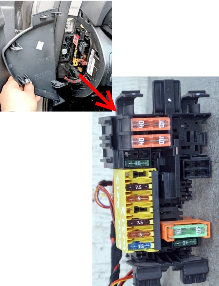
Mercedes GLC X253 Interior Fuse Box Diagram
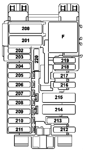
Description
| 200 | 40A Front SAM Control Unit |
| 201 | 50A Front SAM Control Unit |
| 202 | 40A Alarm Siren |
| 203 | 20A Valid for vehicles with gearbox 716: Electric steering column lock control unit |
| 204 | 5A Diagnostic socket |
| 205 | 7.5A Electronic ignition switch control unit |
| 206 | 5A Analog Clock |
| 207 | 15A HVAC Control Unit |
| 208 | 7.5A Instrument cluster |
| 209 | 5A Air Conditioning Control Panel |
| Upper control panel control unit | |
| 210 | 10A Signals from the electronic steering column module control unit |
| 211 | Reserve |
| 212 | Reserve |
| 213 | 5A Signals from the ESP electronic stability control unit |
| 214 | Reserve |
| 215 | Reserve |
| 216 | 7.5A Glove box light |
| 217 | 5A Japan: DSRC Toll Data Communication Control Unit |
| 218 | 7.5A Supplemental Restraint System Control Unit |
| 219 | 5A Weight Sensing System Control Unit |
| 220 | Reserve |
| Relay | |
| F | Relay terminal 15R |
A high-power fuse box is installed in the front passenger footwell.
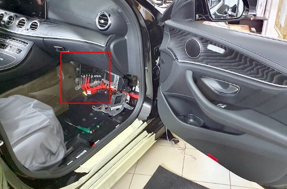
Mercedes GLC X253 Interior Fuse Box Wiring Diagram
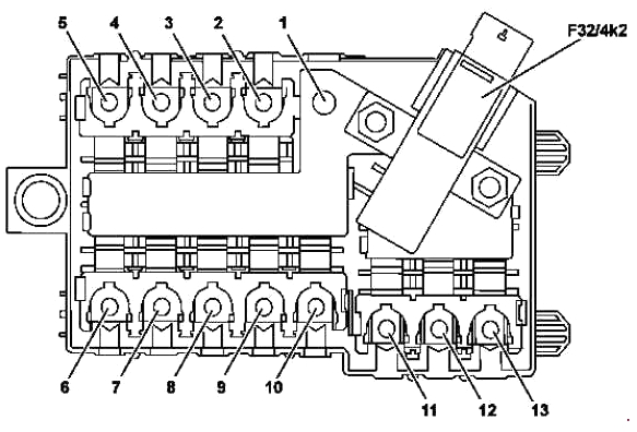
Description
- Engine compartment power fuse box
- 150A Hybrid: Additional battery relay for ECO Start-Stop function
- 40A Fan Controller
- Reserve
- 150A For vehicles with diesel engine: Additional electric heater
- 80A Fuse Box A-Pillar Right
- 150A Rear Fuse and Relay Module
- Reserve
- Reserve
- 60A Valid for vehicles with transmission 725: Control unit for fully integrated transmission management 100A Hybrid with transmission 724: Control unit for fully integrated transmission management
- Reserve
- 40A Rear Fuse and Relay Module
- 50A Fuse Box Pillar A Right
- F32/4k2 – Quiescent current cut-off relay
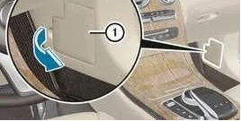
In the same area, on the rack behind the protective cover, there is another fuse box.
Mercedes GLC X253 Fuse Box Diagram
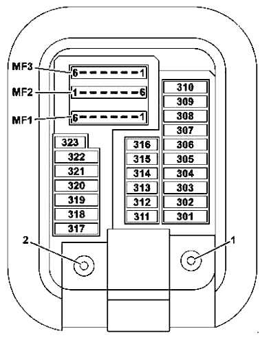
Description
| 301 | 5A Hybrid: Pyro fuse (F63) via high voltage disconnecting device |
| 302 | 30A Front Right Door Control Unit |
| 303 | 30A Rear left door control unit |
| 304 | 20A Valid for vehicles with gearbox 722: Automatic transmission servo drive module for DIRECT SELECT system |
| 305 | 30A Driver Seat Control Unit |
| Driver’s seat heating control unit (before 31.05.2015) | |
| Front seat heating control unit (from 01.06.2015) | |
| 306 | 30A Front Passenger Seat Control Module |
| Front passenger seat heating control unit (before 31.05.2015) | |
| Front seat heating control unit (from 01.06.2015) | |
| 307 | Reserve |
| 308 | 30A USA: Electrical plug connection for Elektric-Brake-Control function |
| 309 | 10A Emergency Call System Control Unit |
| 5A HERMES Control Unit | |
| Communication module of telecommunication services | |
| 310 | Reserve |
| 311 | 10A Electronic control for additional rear passenger compartment fan |
| 312 | 10A Ceiling Control Panel |
| 313 | 10A Hybrid: DC-DC Converter Control Unit |
| 314 | Reserve |
| 315 | 5A Transmission Control Unit |
| On vehicles with a diesel engine: CDI control unit | |
| For vehicles with a petrol engine: ME control unit | |
| 316 | 7.5A Supplemental Restraint System Control Unit |
| 317 | 30A Panoramic sliding sunroof control module (panoramic sliding sunroof) |
| Sliding Sunroof Control Module (Sliding Sunroof) | |
| 318 | 20A Autonomous Heater Control Unit |
| 319 | 5A Hybrid: High Voltage Electric Heater System |
| 320 | 15A AIR BODY CONTROL unit |
| 321 | 5A Japan: DSRC Toll Data Communication Control Unit |
| 322 | 20A Head Unit |
| 323 | 5A Parking assistance control unit |
| MF1/1 | 7.5A Audio display/COMAND |
| Audio Fan Motor (COMAND APS) | |
| MF1/2 | 7.5A Multifunctional Camera Mono |
| Multifunctional stereo camera | |
| MF1/3 | 7.5A Rain and Light Sensor with Additional Functions |
| Ceiling control panel | |
| MF1/4 | 7.5A Driver Seat Control Unit |
| Driver’s seat heating control unit (before 31.05.2015) | |
| Front seat heating control unit (from 01.06.2015) | |
| MF1/5 | 7.5A Front Passenger Seat Control Unit |
| Front passenger seat heating control unit (before 31.05.2015) | |
| Front seat heating control unit (from 01.06.2015) | |
| MF1/6 | 7.5A Signals from the electronic steering column module control unit |
| MF2/1 | 5A Front Left Reversible Seat Belt Tensioner |
| MF2/2 | 5A Audio control panel/COMAND |
| Touch panel (radio receiver Audio 20 or COMAND APS) | |
| MF2/3 | 5A Front Right Reversible Seat Belt Tensioner |
| MF2/4 | 5A Head-up Display |
| MF2/5 | 5A Multimedia Device Connection Module |
| MF2/6 | 5A Hybrid: Electric Air Conditioning Compressor |
| MF3/1 | 5A Front SAM Control Module Terminal 30g Reverse Sense Wire |
| MF3/2 | 5A Radar Sensor Control Unit |
| MF3/3 | Reserve |
| MF3/4 | 5A Driver side instrument panel button block |
| MF3/5 | 5A Rear air conditioning control panel |
| MF3/6 | 5A Tire pressure monitoring system control unit |
Fuses and relays in the luggage compartment of the Mercedes GLC X253
In the trunk of the car under the floor there is a block of fuses and relays. Depending on the configuration, the diagram can be made in 2 versions.
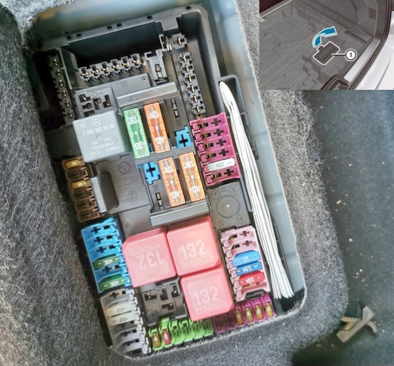
Trunk Fuse Box Diagram (Option 1)
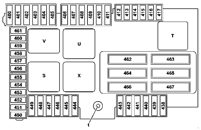
Trunk Fuse Box Diagram (Option 2)
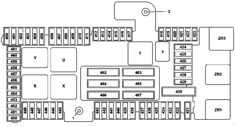
Description
| 400 | 25A AdBlue® Control Unit |
| 401 | 15A AdBlue® Control Unit |
| 402 | 20A AdBlue® Control Unit |
| 403 | 30A Before 11/30/2015: Front passenger seat semi-electric adjustment switch |
| 25A From 01.12.2015: Switch for partially electric adjustment of front passenger seat position | |
| 404 | 30A Before 11/30/2015: Driver’s seat partially electric adjustment switch |
| 25A From 01.12.2015: Switch for partially electric adjustment of driver’s seat position | |
| 405 | Reserve |
| 406 | 30A Front Left Door Control Unit |
| 407 | Reserve |
| 408 | 30A Rear Right Door Control Unit |
| 409 | Reserve |
| 410 | 15A Receiver for remote control of independent heater |
| Antenna switch for telephone and independent heater | |
| 411 | 30A Front Left Reversible Seat Belt Tensioner |
| 412 | 7.5A Hybrid: Battery Management System Control Unit |
| 413 | 5A Tailgate Drive Control Unit |
| 414 | 5A Tuner module (TV tuner, digital radio (DAB)) or satellite radio SIRIUS) |
| 415 | 5A Chamber Lid Control Unit |
| Air freshener generator | |
| 416 | 7.5A Mobile Antenna Amplifier/Compensator |
| Mobile phone contact board | |
| 417 | 5A 360° Camera Control Unit |
| Rear view camera | |
| 418 | 5A Rear seat heating control unit |
| AIRSCARF system control unit | |
| 419 | 5A Front passenger seat lumbar support adjustment control unit |
| 420 | 5A Driver’s seat lumbar support adjustment control unit |
| 421 | Reserve |
| 422 | Reserve |
| 423 | 5A Speaker Amplifier Control Unit |
| 424 | 15A AIR BODY CONTROL Plus control unit |
| Valid for vehicles with engine 276: Motorsound control unit | |
| 425 | Reserve |
| 426 | Reserve |
| 427 | Reserve |
| 428 | Reserve |
| 429 | Reserve |
| 430 | Reserve |
| 431 | 25A Multifunctional control unit for special vehicles |
| 432 | 25A Multifunctional control unit for special vehicles |
| 433 | 20A Trailer Recognition Control Unit |
| 434 | 30A Trailer Recognition Control Unit |
| 435 | 25A Trailer Recognition Control Unit |
| 436 | 15A Trailer Recognition Control Unit |
| 437 | 25A Trailer Recognition Control Unit |
| 438 | 30A AC/DC Converter Control Unit |
| 439 | Reserve |
| 440 | 30A Rear seat heating control unit |
| AIRSCARF system control unit | |
| 441 | 30A AIRSCARF system control unit |
| 442 | 25A Fuel Pump Control Unit |
| 443 | 30A Front Right Reversible Seat Belt Tensioner |
| 444 | 15A Tablet Computer Electrical Plug Connection |
| 445 | 15A Socket in the Trunk |
| 446 | 15A Cigarette lighter with illuminated ashtray front (socket inside) |
| 447 | 15A 12V socket in the rear right center console |
| 448 | 10A Valid for vehicles with gearbox 722, 725: Parking lock capacitor |
| 449 | Valid for vehicles with engine 626: Fuel filter element with integrated heating |
| Hybrid: Sound Generator | |
| 450 | 5A Rear SAM Control Unit |
| 451 | 5A Fuel Pump Control Unit |
| AdBlue® Control Unit | |
| 452 | 5A Integrated radar sensor rear bumper outside right |
| Integrated radar sensor rear bumper outside left | |
| Radar sensor in the rear bumper in the center | |
| Radar sensor in the rear bumper on the right outside | |
| Radar sensor in the rear bumper on the left outside | |
| 453 | 5A Radar sensor in the front bumper on the left |
| Radar sensor in the front bumper, right | |
| COLLISION PREVENTION ASSIST control module | |
| 454 | 7.5A Valid for vehicles with gearbox 722: Control unit for fully integrated automatic transmission control system |
| 5A AdBlue® Control Unit | |
| 455 | 5A AC/DC Converter Control Unit |
| 456 | 5A Front Far-Range Radar Sensor |
| Electrical control module DISTRONIC | |
| 457 | 5A Hybrid: |
| DC-DC converter control unit | |
| Power electronic equipment control unit | |
| 458 | 5A Keyless trunk lid opening module under rear bumper |
| 459 | 5A Hybrid: Charger |
| 460 | 10A kEyLESS-GO Control Unit |
| 461 | 5A Antenna amplifier FM 1, AM, CZ and KEYLESS-GO |
| 462 | 40A Speaker Amplifier Control Unit |
| 463 | 30A Rear window heating (R1) via rear window noise suppression capacitor |
| 464 | 40A Tailgate Drive Control Unit |
| Tailgate Drive Control Unit | |
| 465 | 40A Rear SAM Control Unit |
| 466 | 40A Rear SAM Control Unit |
| 467 | 40A Valid for vehicles with engine 626: Fuel filter element with integrated heating |
| Relay | |
| S | Terminal 15 interior relay |
| T | Rear window heating relay |
| U | Relay for cup holder and sockets 2nd row of seats |
| V | AdBlue® Relay |
| X | Relay for the refrigeration box and sockets for the 1st row of seats/trunk |
| Y | Backup relay |
| ZR1 | Valid for vehicles with engine 626: Fuel filter heating relay |
| ZR2 | Backup relay |
| ZR3 | Backup relay |
Fuses and relays under the hood of the Mercedes GLC X253
On the left side of the engine compartment there is a fuse and relay box, the box is covered with a protective cover.
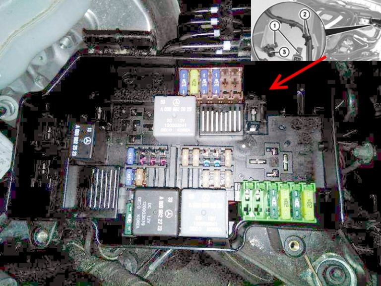
Under Hood Fuse and Relay Box Diagram
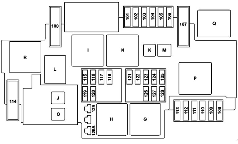
Description
| 100 | 40A Hybrid: Vacuum Pump |
| 101 | 15A Cable End Joint Terminal 87/2 |
| 102 | 20A Cable End Joint Terminal 87/1 |
| 103 | 15A Cable End Joint Terminal 87/4 |
| 104 | 15A Cable End Joint Terminal 87/3 |
| 105 | 15A Valid for vehicles with gearbox 722.9 (except 722.930): Control unit for additional transmission oil pump |
| 106 | Reserve |
| 107 | 60A Valid for engine 274.9: Electric coolant pump |
| 108 | 20A LED Static Lights: |
| Front right headlight | |
| High Performance LEDs or LED dynamic headlights: | |
| Front left headlight | |
| Front right headlight | |
| 109 | 30A Windscreen Wiper Motor |
| 110 | 20A LED Static Lights: |
| Front left headlight | |
| High Performance LEDs or LED dynamic headlights: | |
| Front left headlight | |
| Front right headlight | |
| 111 | 30A Starter |
| 112 | 15A Hybrid: Accelerator Pedal Position Sensor |
| 113 | Reserve |
| 114 | 40A AIR BODY CONTROL system compressor |
| 115 | 15A Horn left and horn right |
| 116 | Reserve |
| 117 | Reserve |
| 118 | 5A Hybrid: Signals from the ESP electronic stability control unit |
| 119 | 15A Cable End Sleeve Terminal 87 C2 |
| 120 | 5A Cable End Sleeve Terminal 87 C1 |
| 121 | 5A Signals from the ESP electronic stability control unit |
| 122 | 5A CPC Relay |
| 123 | Reserve |
| 124 | Reserve |
| 125 | 5A Front SAM Control Unit |
| 126 | 5A Transmission Control Unit |
| On vehicles with a diesel engine: CDI control unit | |
| For vehicles with a petrol engine: ME control unit | |
| 127 | 5A Hybrid: Voltage Dropout Suppressor |
| 128 | 5A Front left headlamp and exterior lighting switch |
| 129 | 30A Starter Terminal 50 Relay |
| 129A | 30A Hybrid: Starter Terminal 50 Relay |
| Relay | |
| G | Relay terminal 15, engine compartment |
| H | Starter terminal 50 relay |
| I | Hybrid: Vacuum Pump Relay (+) |
| J | CPC relay |
| K | Valid for vehicles with gearbox 722.9 (except 722.930): Oil pump relay |
| L | Horn relay |
| M | Windscreen wiper heating relay |
| N | Relay terminal 87M |
| O | Starter terminal 15 relay |
| P | Valid for engine 274.9: Coolant pump relay |
| Q | Hybrid: Vacuum Pump Relay (-) |
| R | AIR BODY CONTROL system relay |