We consider fuses and relays in the Mercedes w221 car – 2005, 2006, 2007, 2008, 2009, 2010, 2011, 2012, 2013 years of manufacture.
Fuses and relays under the hood Mercedes w221
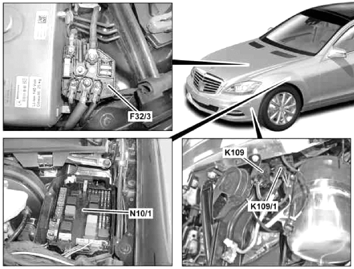
Description
- F32/3 – Power fuse box
- N10/1 – Main fuse and relay box
- K109 (K109/1) – Vacuum pump relay
Fuse and Relay Box Diagram
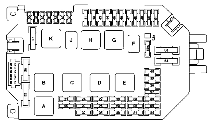
Description
| 20 | 10A CDI System Control Unit |
| ME control unit | |
| 21 | 20A Cable Lug Electrical Circuit Terminals 87 M1i |
| CDI system control unit | |
| Fuel pump relay | |
| Dosing valve | |
| 22 | 15A Cable Lug Electrical Circuit Terminals 87 |
| 23 | 20A Cable Lug Electrical Circuit Terminals 87 |
| Cable lug electrical circuit terminals 87 M2e | |
| Cable lug electrical circuit terminals 87 M2i | |
| SAM control unit with fuse and relay module in the rear compartment | |
| 24 | 25A Cable Lug Electrical Circuit Terminals 87M1e |
| CDI system control unit | |
| 25 | 7.5A Instrument cluster |
| 26 | 10A Front Left Headlight |
| 27 | 10A Front Right Headlight |
| 28 | 7.5A |
| EGS control unit | |
| Control unit integrated into automatic transmission (VGS) | |
| 29 | 5A SAM control unit with rear fuse and relay module |
| 30 | 7.5A CDI System Control Unit |
| ME control unit | |
| Fuel pump control unit | |
| 31 | 5A S 400 Hybrid: Electric air conditioning compressor |
| 32 | 15A Control unit of additional gearbox oil pump |
| 33 | 5A From 1.9.10: ESP control unit |
| S 400 Hybrid: | |
| Battery management system unit | |
| DC/DC Converter Control Unit | |
| Power electronics control unit | |
| 34 | 5A S 400 Hybrid: Brake Energy Regeneration Control Unit |
| 35 | 5A Electric Parking Brake Control Unit |
| 36 | 10A Diagnostic socket |
| 37 | 7.5A EZS Control Unit |
| 38 | 7.5A Central Interface Control Unit |
| 39 | 7.5A Instrument cluster |
| 40 | 7.5A Upper Control Panel |
| 41 | 30A Slave Wiper Motor |
| 42 | 30A Main Wiper Motor |
| 43 | 15A Cigarette Lighter with Illuminator, Front |
| 44 | Reserve |
| 45 | 5A S 400 Hybrid: |
| Circulation pump 1 power electronic devices | |
| 46 | 15A ABC (Active Body Level Control) control unit |
| AIRMATIC control unit with ADS | |
| 47 | 15A Electric motor for adjusting the steering column up and down |
| 48 | 15A Electric motor for adjusting the steering column forward and backward |
| 49 | 10A Electronic Steering Column Module |
| 50 | 15A KLA Control Unit |
| 51 | 5A COMAND Display |
| Display of the split image system SPLITVIEW (split image system) | |
| 52a | 15A W221: |
| Left horn | |
| Right horn | |
| 52b | 15A W221, C216: |
| Left horn | |
| Right horn | |
| 53 | Reserve |
| 54 | 40A Air conditioning system air recirculation unit |
| 55 | 60A Petrol Engines: Electric Air Pump |
| 56 | 40A Compressor unit of the AIRmatic system |
| 57 | 30A Windscreen wiper heating |
| 60 | 5A Electro-hydraulic power steering |
| 61 | 7.5A Passive safety systems control unit |
| 62 | 5A Night Vision Control Unit |
| 63 | 15A Fuel filter condensate sensor with heating element |
| 64 | 10A W221: |
| NECK-PRO headrest solenoid coil on the driver’s seat back | |
| NECK-PRO headrest solenoid coil on the back of the right front seat | |
| 65 | 15A Valid from 1.6.09: 12 volt plug connection in glove compartment |
| 66 | 7.5A DTR Control Module (Distronic) |
| Relay | |
| A | Air pump relay |
| B | Air Suspension Compressor Relay |
| C | relay terminal 87, engine |
| D | Relay terminal 15 |
| E | Electrical circuit relay terminal 87 chassis |
| F | Sound signal relay |
| G | Relay terminal 15R |
| H | Relay electrical circuit terminal 50, starter |
| J | Relay of electric circuit terminal 15, starter |
| K | Windscreen wiper heating relay |
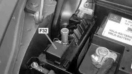
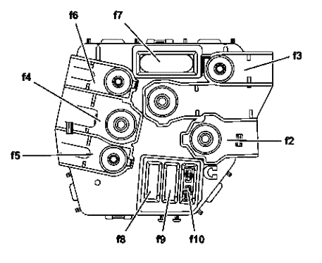
A high-power fuse box is located near the battery.
High Power Fuse Box Schematic (Option 1)
Description
- F32f1 – Starter 400A
- F32f2 – Except Engine 642: Generator 150A / Engine 642: Generator 200A
- F32f3 – 150
- F32f4 – Suction electric fan of the engine and air conditioner with integrated regulator 150A
- F32f5 – Engine 642: Additional heater PTC 200A
- F32f6 – SAM control unit with fuse and relay module, front 200A
- F32f7 – ESP 40A control unit
- F32f8 – ESP control unit 25A
- F32f9 – SAM control unit with fuse and relay module, front 20A
- F32f10 – On-board network control unit 7.5A
High Power Fuse Box Schematic (Option 2)
Description
| 3 | 150A SAM Control Unit with Rear Fuse and Relay Module |
| 4 | 150A ECO Start-Stop function relay |
| S 400 Hybrid: DC/DC converter control unit | |
| Windscreen heating control unit | |
| 5 | 125A Multifunctional Special Vehicle Control Unit (MSS) |
| 40A S 400 Hybrid: Vacuum Pump | |
| 6 | 80A Right side fuse box in front panel |
| 7 | 150A Multifunctional Special Vehicle Control Unit (MSS) |
| Engine 629, 642, 651: PTC Additional Heater | |
| 8 | 80A Front SAM Control Unit with Fuse and Relay Module |
| 9 | 80A Left Fuse Box in Front Panel |
| 10 | 150A SAM Control Unit with Rear Fuse and Relay Module |
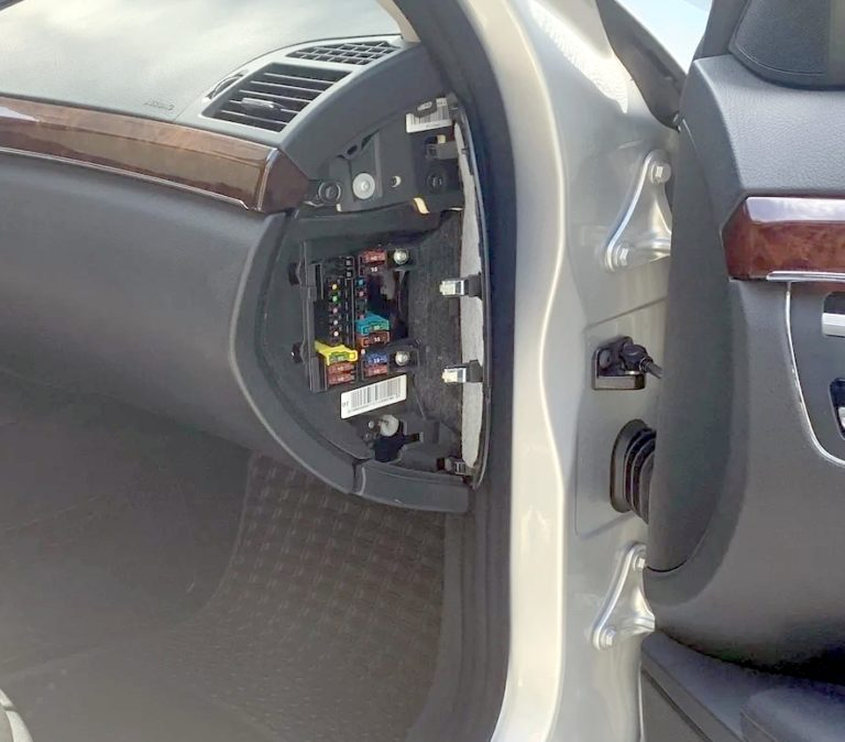
Fuses and relays in the cabin of Mercedes w221
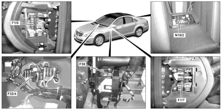
Description
- F1/6 – Fuse box in the instrument panel, right
- F1/7 – Fuse box in the instrument panel, left
- F32/4 – Power fuse box
- F38 – Emergency battery fuse
- N10/2 – Rear fuse and relay box
Fuse box in the panel on the left
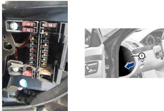
Fuse box diagram in left panel
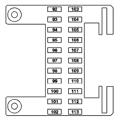
Description
| 92 | 40A Front left seat control unit |
| 93 | 7.5A Passive safety system control unit |
| Control unit for weight sensing system (WSS) (USA) | |
| 94 | Not used |
| 95 | Not used |
| 96 | 5A RDK control unit (tire pressure monitoring system (Siemens)) |
| 97 | 7.5A W221: Control unit Audio – Video – Controller (multimedia entertainment system in the rear compartment) |
| 98 | Not used |
| 99 | Not used |
| 100 | Not used |
| 101 | 10A Display left in the rear of the cabin |
| Display right in the rear of the cabin | |
| 102 | 40A Seat control unit front right |
| 103 | 7.5A ESP control unit |
| 104 | 40A Audio Tuner Control Unit |
| 105 | Not used |
| 106 | Electronic Toll Collection (ETC) Control Unit (Japan) |
| 107 | 5A C216: SDAR Control Unit |
| 108 | 5A Rear Air Conditioner Control Unit |
| 109 | 15A W221: Intermediate plug connection for rear electric fan |
| 110 | 7.5A W221: |
| Multicontour seat back control unit rear left | |
| Multicontour seat back control unit rear right | |
| 111 | 5A HBF Control Unit |
| 112 | 5A W221: |
| Front left door control unit | |
| Front right door control unit | |
| 113 | Not used |
Fuse box in the panel on the right
Fuse box diagram in the panel on the right
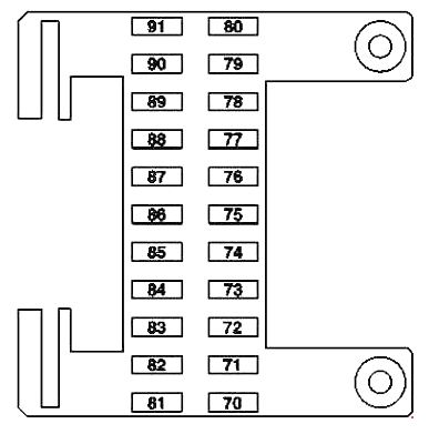
Description
| 70 | 40A C216: Right Door Control Unit |
| W221: Control unit in front right door | |
| 71 | 15A KEYLESS-GO Control Unit |
| 72 | 7.5A S 400 Hybrid: Pyrotechnic disconnecting element |
| 73 | 5A COMAND control unit (Japan) |
| Emergency call system control unit | |
| 74 | 30A HDS Control Unit (Remote Trunk Lid Closing) |
| 75 | 10A S 400 Hybrid: |
| Battery management system unit | |
| Power electronics control unit | |
| 76 | Engine 642.8: AdBlue® Supply Relay |
| 15A S 400 Hybrid: Vacuum Pump Relay (+) | |
| 77 | 50A Acoustic Amplifier |
| 78 | 25A S 65 AMG with 275 engine: Additional fan relay |
| Engine 642.8: AdBlue® Supply Relay | |
| 15A Engine 157, 278; S 400 Hybrid, CL 63 AMG: Charge air cooler circulation pump | |
| 79 | 7.5A Alarm Siren |
| 80 | 40A C216: Control unit in left door |
| W221: Control unit in front left door | |
| 81 | 30A C216: Rear compartment systems control unit |
| 40A W221: Rear left door control unit | |
| 82 | 30A C216: Rear compartment systems control unit |
| 40A W221: Rear right door control unit | |
| 83 | 30A Automatic transmission servo module for the “DIRECT SELECT” system |
| 84 | 20A Digital Sound Processor |
| 85 | 10A AMG: Illuminated door sills |
| 86 | Reserve |
| 87 | Reserve |
| 88 | Reserve |
| 89 | Reserve |
| 90 | 20A C216: STH heater (autonomous heating system) |
| W221: Heater STH (autonomous) or ZUH (additional) | |
| 91 | 5A Receiver unit for remote radio control of autonomous heater STH |
| S 400 Hybrid: Front control unit SAM with fuse and relay module |
Mercedes w221 rear fuse box and relay
Located behind the armrest in the rear seat.
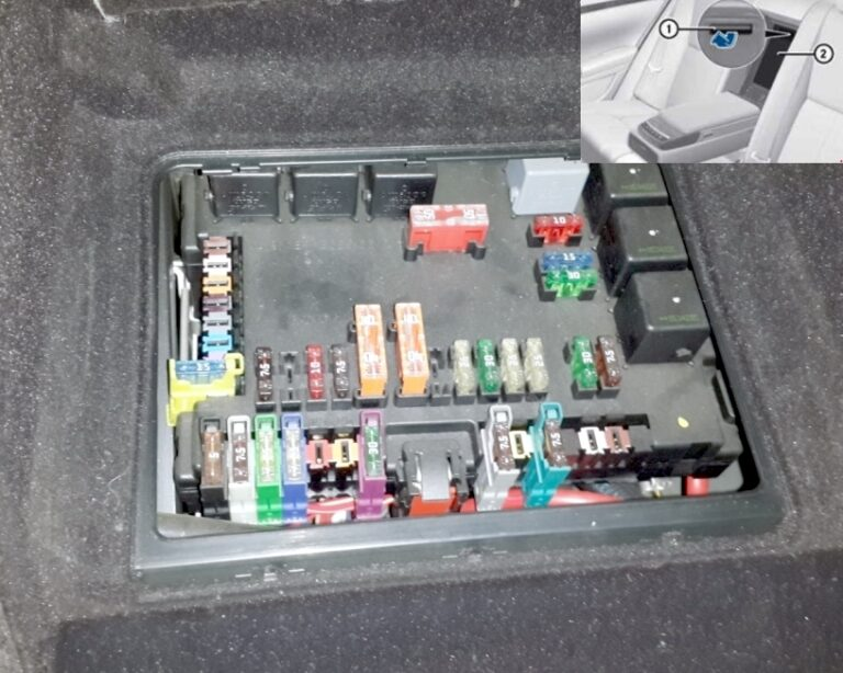
Rear Armrest Fuse Box Diagram
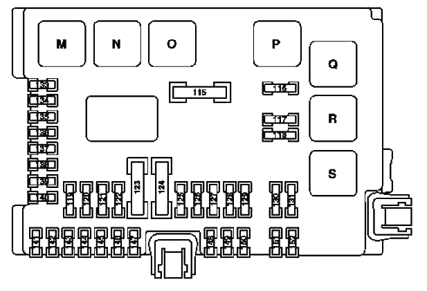
Description
| 115 | 50A Rear Window Defogger |
| 116 | 10A Engine 157, 275, 278: Charge air cooler circulation pump |
| Engine 156: Engine Oil Cooler Circulation Pump | |
| S 400 Hybrid: Circulation pump 2 power electronics | |
| 117 | 15A Rear Cigarette Lighter |
| 118 | 30A Engine 629, 642: Fuel Pump |
| 15A S 400 Hybrid: Circulation pump 1 power electronics | |
| 15A Engine 642.8, 651 from 1.6.11: Refrigerant compressor with electromagnetic clutch | |
| 119 | 7.5A Central Control Panel Front |
| 120 | Reserve |
| 121 | 10A Audio Tuner Control Unit |
| 122 | 7.5A COMAND control unit |
| 123 | 40A W221: Front right reversible seat belt tensioner |
| 124 | 40A W221: Front left reversible seat belt tensioner |
| 125 | 5A Voice Buzzer (SBS) |
| 126 | 25A Ceiling Control Panel |
| 127 | 30A Seat Back Lower Pump |
| Multi-contour seat pneumatic pump | |
| Pneumatic pump for dynamic seat adjustment | |
| 128 | 25A Engine 156, 157, 272, 273, 275, 276, 278, 642: Fuel Pump Control Unit |
| 129 | 25A UHI(Universal Cell Phone Interface) Control Unit/Ceiling Control Panel |
| 130 | 30A Electric Parking Brake Control Unit |
| 131 | 7.5A Antenna Amplifier Module Above Rear Window |
| 133 | 15A Trailer Recognition Control Unit |
| 5A Rear view camera | |
| 134 | 15A Socket in Luggage Compartment |
| 135 | 7.5A Sensor Radar Control Unit (SGR) |
| PTS control unit (PARKTRONIC) | |
| 136 | 7.5A Engine 642.8: AdBlue® Control Unit |
| 137 | 7.5A From 1.9.10: Rear view camera |
| 138 | 5A Navigation Processor (Taiwan, up to 8/31/10) |
| Emergency call system control unit | |
| TV/Tuner Plug Connection (Japan) | |
| 139 | 15A Cooling box in the back of the rear seat |
| 140 | 15A Cigarette lighter plug with ashtray lighting, rear |
| 115V socket | |
| 141 | 5A Rear View Camera Control Unit |
| Rear view camera power module | |
| 142 | 7.5A PTS control unit (PARKTRONIC) |
| Sensor Radar Control Unit (SGR) | |
| Control unit for video sensors and radar sensors (since 1.9.10) | |
| 143 | 25A Rear Seat Control Unit |
| 144 | 25A Rear Seat Control Unit |
| 145 | 20A AHV towing hitch connector, 13-pin |
| 146 | 25A Trailer Recognition Control Unit |
| 147 | Reserve |
| 148 | 25A Terminal 30 Panoramic Sliding Sunroof End Sleeve |
| 149 | 25A Panoramic Sliding Sunroof Control Module |
| 150 | 7.5A Combo TV Tuner (Analog/Digital) |
| TV/Tuner Plug Connection (Japan) | |
| 151 | 20A Trailer Detection Control Module 25A Electric Parking Brake Control Module |
| 152 | 25A DC/AC Converter Control Unit 7.5A Antenna Amplifier Module Above Rear Window |
| Relay | |
| M | Relay terminal 15 (2) / reserve 1 (changeover contact relay) |
| N | Relay terminal 15R |
| O | Socket relay |
| P | Rear window heating relay |
| Q | Engine 156, 157, 275, 278, 629: Circulation pump relay |
| S 400 Hybrid: Circulation pump relay 2 power electronics | |
| R | Cigarette lighter relay |
| S | Engine 642, except 642.8: Fuel pump relay |
| Engine 642.8, 651 from 1.6.11: Electromagnetic clutch of refrigerant compressor | |
| S 400 Hybrid: Circulation pump relay 1 power electronics | |
Passenger Side Power Fuse Box Diagram
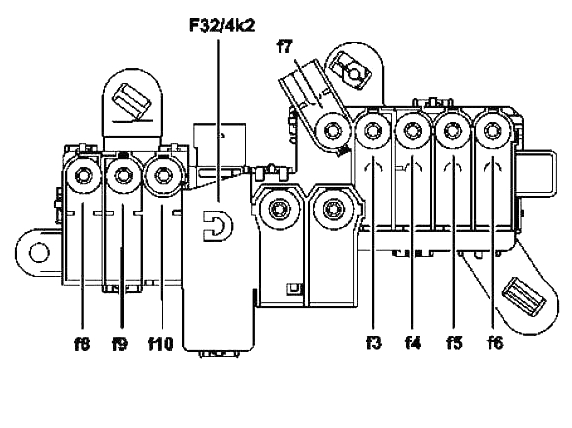
Description
| 2 | 400A Generator (G2) |
| 3 | 150A Electro-hydraulic power steering |
| Engine 629, 642:End of glow plug time | |
| 4 | Passenger compartment power fuse box F32/4 |
| 5 | 100A Electric suction fan for engine and air conditioner with integrated regulator |
| 6 | 150A Front SAM Control Unit with Fuse and Relay Module |
| 7 | 40A ESP control unit |
| S 400 Hybrid: Brake Energy Regeneration Control Unit | |
| 8 | 25A ESP control unit |
| S 400 Hybrid: Brake Energy Regeneration Control Unit | |
| 9 | 25A Front SAM Control Unit with Fuse and Relay Module |
| 10 | Reserve |
| Relay | |
| F32/4k2 | Quiescent current cut-off relay |
Mercedes w221 fuses and relays. Mercedes w221 fuse diagram.