We consider fuses and relays in the Mercedes-Benz Atego 2nd generation car, manufactured in 2004, 2005, 2006, 2007, 2008, 2009, 2010, 2011, 2012, 2013, 2014, 2015, 2016, 2017, 2018.
Fuses in the cabin of Mercedes-Benz Atego 2
The fuse and relay box is located in the control panel on the passenger side. The box is covered with a protective cover, which has a diagram of the box.
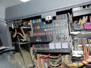
Where are the fuses on a Mercedes-Benz Atego 2
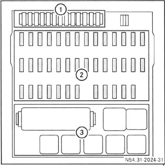
Description
- Spare fuses
- Main fuse compartment
- Relay
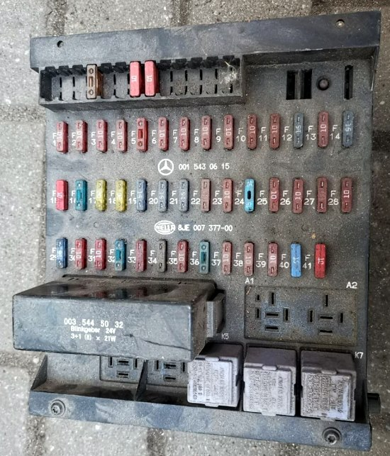
Mercedes-Benz Atego 2 fuse box diagram
Description
- 10A Rear fog lights, including on trailer
- 10A Instrument cluster lighting/switch lighting, headlamp cleaner, headlamp range control, Mounting block – terminal 58
- 10A Additional direction indicators
- 10A Sunroof, 24V Radio, Handbrake – Terminal 30
- 10A Work Light, LSVA (Low Load Vehicle Availability Charge) – Terminal 30
- 10A Backup
- 15A Mounting Block – Clamp D+
- 10A Mirror heating system
- 15A 24V Power Sockets
- 10A Digital tachograph, instrument cluster, diagnostic connector – terminal 30
- 20A Trailer Power Socket – Terminal 30
- 20A Trailer ABS Power Socket – Terminal 30
- 10A Interior Lighting, Toll Collect System – Clamp 30
- 10A Headlight cleaner
- 10A Three-phase alternator, gearbox, LSVA (heavy load vehicle surcharge) – terminal 15
- 10A Power take-off mechanisms
- 20A Heater Fan, Air Conditioner
- 5A Instrument cluster, radio, telephone, speakerphone, fax – terminal 15R
- 10A Cigarette Lighter
- 15A Front Passenger Side Switch Block
- 15A Driver’s Door Switch Block
- 10A Windscreen Washer, Hazard Warning Light – Clamp 30
- 10A Low beam right
- 10A Low beam left
- 10A High beam right
- 10A High beam left, high beam indicator light
- 10A Tail light, parking light, left side marker lights, trailer socket, Toll Collect
- 10A Tail light, parking light, right side marker lights, trailer socket
- 15A Gearbox Control System
- 10A Engine Operation Control – Terminal 15, GGVSE: Emergency Switch NOT-AUS
- 10A Driver’s door switch block, outside rearview mirror position setting, exhaust gas aftertreatment system block – terminal 15
- 10A All-wheel drive, ESP® system, additional water heating system
- 10A Windscreen Washer, Hazard Warning Lights, Trailer Power Socket – Terminal 15
- 10A Brake light, Reverse light, Trailer power socket
- 10A Condensation Sensor, Trailer ABS Power Socket – Terminal 15
- 15A Additional water heating system
- 10A Windscreen Washer
- 10A Digital tachograph, instrument cluster, airbag – terminal 15
- 10A Horn, Toll Collect, Diagnostic Connector, FleetBoard®, Distributor – Terminal 15
- 10A Differential Lock Mechanism
- 10A Seat heating system
Relay
- K3 ABS/BS/EPB disabled
- K4 Starter/Battery Heater Relay
- K5 D+
- K6 Stop light
- K7 Reversing light
Additional Sections Scheme
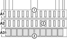
Description
A1
- 10A Auxiliary Heating System Clock, FleetBoard® System, Toll Collect System – Terminal 30
- 20A Additional heating system
- 15A Central locking system
- 15A Comfort Control Lock System
- 10A Electronic Brake System, Portable Lamp Power Socket – Terminal 15
- 15A 12V Power Socket
- 10A Voltage Transformer 24V/12V 8A/15A Voltage Transformer 24V/12V 15A
- 10A Central locking system / comfort locking system, radio remote control, retarder
- 10A Compressed Air Dryer
- 15A Distributor – terminal 30
- 15A Emission Control System Unit – Terminal 30
- 10A Tail lift
- 10A Gearbox Control System
- 10A Working light, retarder
A2
- 20A Windscreen heating system
- 10A Daytime Running Lights
- 10A Windscreen heating system
- 10A Transmission Oil Cooling System, Cooling Box / 25A Allison Transmission Oil Cooling System
- 15A Electronic-hydraulic autonomous power steering – clamp 30
- 10A Electronic-hydraulic autonomous power steering – clamp 15
- 10A Additional headlight
- 10A Flashing beacon
- 15A Electronic Brake System – Terminal 30
- 10A Telephone/Navigation Control Panel, Mobile Phone – Terminal 30
- 10A Backup
- 10A Telephone/Navigation Control Panel, Mobile Phone – Terminal 15
- 20A Windscreen heating system
- 15A Electronic Brake System – Terminal 30
Mercedes-Benz Atego 2 fuses and relays. Mercedes-Benz Atego 2 fuse diagram.