We consider fuses and relays in the Mercedes w220 car with the designation S280, S320, S350, S430, S500, S600, S55 AMG, S63 AMG, S65 AMG, S320 CDI, S400 CDI — 1998, 1999, 2000, 2001, 2002, 2003, 2004, 2005.
Fuses and relays under the hood Mercedes w220
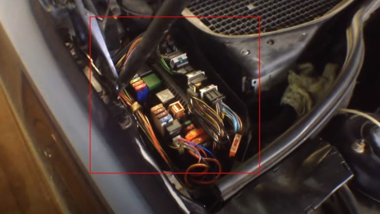
There are several fuse boxes in the engine compartment, 2 boxes on the right side and 1 box on the left side of the engine compartment.
Right fuse box diagram
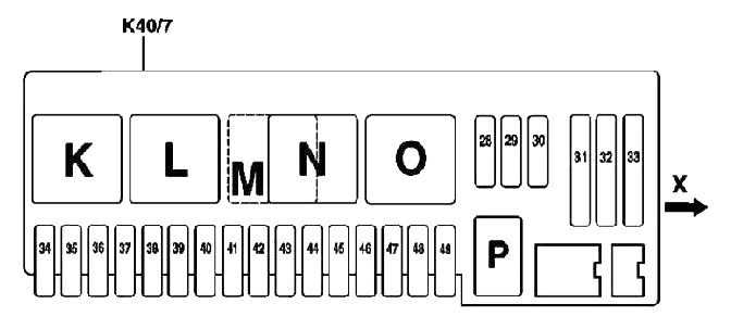
Description
| 28 | 15A Horn Relay (K40/7kP) |
| 29 | 20A Relay for electronic engine and chassis control systems (K40/7kK) |
| 30 | 20A Relay for electronic engine and chassis control systems (K40/7kK) |
| 31 | 40A Air pump relay (K40/7kN) |
| 32 | 40A Air Compressor Relay (K40/7kO) |
| 33 | 40A Heating Air Circulation Unit (A32) |
| 34 | 5A Traction control system control unit (N47) |
| 35 | 15A from 09.2002 – If equipped with steering wheel heating (code 443): Steering wheel heating (R22/4) |
| 36 | 7.5A With Distronic system (code 219a): DTR system control unit (N63/1) |
| 37 | 15A Cable connector class 87 (Z7/5): |
| • control unit of the electronic module of the AT control lever (N15/5) | |
| • EGS system control unit (N15/3) | |
| 38 | 5A Interior trunk lid actuator button (KIT) |
| 39 | 40A Front right door control unit (N69/2) |
| 40 | 10A If xenon headlights are present (code 612b): |
| Headlamp range control system control unit (N71) | |
| 41 | 20A If there is an independent heating system (code 228): via the cable connector of terminal 30 (soldered sleeve in the wiring harness) (Z7/26): |
| • independent heater (STH) or additional heater (ZUH) (A6) | |
| • STH remote control receiver (A6/1) | |
| 42 | 20A • via cable connector cl. 87 (Z7/24) (before 09.2002): |
| – additional fan unit relay (K25) | |
| 43 | 25AFor diesel engines only: |
| • via cable connector terminal 87 (Z7/47) (up to 09.2002):– CDI control unit (N3/9)– starter relay (K40/kL) in the front right relay and fuse box (K40/7) | |
| 44 | 7.5A For diesel engines only: |
| • CDI control unit (N3/9) | |
| • intake manifold heater, in the front right relay and fuse box (K40/7) | |
| 44 | 10A Via cable connector terminal 87D2 (Z7/48) (before 09.2002): |
| • CDI control unit (N3/9) | |
| • starter relay (K40/kL) in the front right relay and fuse box (K40/7) | |
| • electric fan-blower of the engine and air conditioner with a built-in regulator (M4/7) | |
| • low-temperature circuit circulation pump (M44) | |
| 45 | — |
| 46 | 5A With Active Body Control (ABC): |
| • ABC system control unit (N51/2)If equipped with air suspension: | |
| • Airmatic system control unit with ADS (N51) | |
| 47 | 10A Multifunctional sensor KLA (B31/1) |
| Fan electric motor in protective electrical equipment box (M2/2) | |
| Multifunctional sensor KLA (B31/1) (before 09.2002) | |
| Control of the relay of the additional fan unit of the engine cooling system or AT oil (K25) via a plug connector (X22/3) (before 09.2002) | |
| Via cable electrical circuit of fans (Z5/1) (before 09.2002) | |
| • multifunctional sensor KLA (B31/1) (before 09.2002) | |
| • control of the relay of the additional fan unit of the engine cooling system or oil in the AT (K25) via a plug connector (X22/3) (before 09.2002) | |
| • electric motor of the fan in the protective box of electrical equipment (M2/2) (before 09.2002) | |
| 48 | 7.5A Control unit for blower fan (N65/2) / (from 09.2002 – missing) |
| 48 | 7.5A Electric fan-blower of the engine and air conditioner with built-in regulator (M4/7) / (from 09.2002 – absent) |
| 49 | 15A Via cable connector of protected terminal 15 (Z3/29): |
| • ignition coils (T1/1) – (T1/8) | |
| • radio interference suppression capacitor (C4), for Japan and USA |
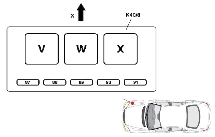
An additional fuse box is located nearby.
Additional fuse box diagram on the right
Description
- V – Motronic system relay
- W – Boost air relay
- X – Fuel module relay in the tank (fuel pump relay)
- 87 – 20A Motronic (K40/8kV), M275/M113 E55 AMG
- 88 – 20A Motronic (K40/8kV), M275/M113 E55 AMG
- 89 – Reserve
- 90 – 10A Air boost relay (K40/8kW), M275/M113 E55 AMG
- 91 – Reserve
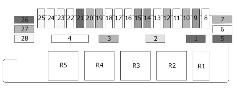
The fuse and relay box is located on the left side of the engine compartment.
Left fuse and relay box diagram
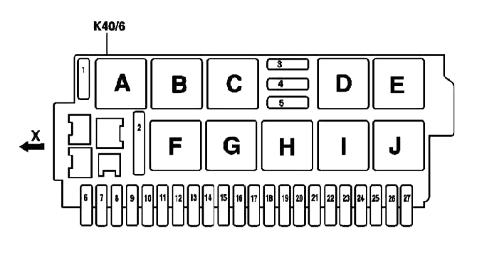
Description
| 1 | 40A Windscreen wiper heating relay (K40/6kA) |
| 2 | 50A Relay for injection/drainage pumps (K40/6kF) |
| 3 | 15A Horizontal adjustment of the steering column position: |
| • Relay 1 for longitudinal adjustment of the steering column (K40/6kD) | |
| • Relay 2 for longitudinal adjustment of the steering column (K40/6kE) | |
| 4 | 15A Vertical adjustment of the steering column position: |
| • Relay 1 for steering column angle adjustment (K40/6kI) | |
| • Relay 2 for steering column angle adjustment (K40/6kJ) | |
| 5 | 40A Windscreen Wiper ON/OFF Relay (K40/6kH) |
| 6 | 7.5A Additional heater switch (S4/3) / (from 09.2002 – absent) |
| 7 | — |
| 8 | — |
| 9 | 30A With air suspension: |
| • Airmatic system control unit with ADS (N51) | |
| with the Active Body Clearance Control (ABC) system: | |
| • ABC system control unit (N51/2) | |
| 10 | 15A Windscreen washer pump (M5/1) |
| 11 | 5/ 15A Cigarette lighter with front ashtray light (R3) / (from 09.2002 – VISC power split point X137/1) (from 09.2002 – Japan models only) |
| 12 | 7.5A Dynamic seat belt locking (A60) / (from 09.2002 – not available) |
| 13 | 40A Front left door control unit (N69/1) |
| 14 | — |
| 15 | — |
| 16 | 7.5A Brake light switch (S9/1) |
| 17 | — |
| 18 | 5A If you have a GSM mobile phone (D2B) (basic equipment) (code 317): |
| • mobile phone plug connector (X39/39) | |
| If you have a MB GSM (D2B) phone (code 316): | |
| • D2B interface for landline telephone (A59) | |
| If you have an MB GSM (D2B) telephone (code 316) with the Tele Aid emergency call system (code 347): | |
| • Tele Aid system control unit (A35/8) | |
| If you have an MB GSM telephone (D2B) (code 316) with the E-Call emergency call system (code 349) via the cable connector of terminal 15R (Z3/12): | |
| • D2B interface for landline telephone (A59) | |
| • Range switching control unit (N96) | |
| • E-Call system control unit (A35/8) (since 09.2002 – If there is an MB GSM telephone (D2B) (code 854): | |
| • via connector 15R(Z3/1) of circuit 2: – frequency selection control unit (N96) – E-Call control unit (A35/8) – D2B interface for mobile phone (A59/1) | |
| 19 | 5A since 09.2002 – front left (A76) and right (A76/1) reversible emergency tensioners |
| 20 | 5A Instrument cluster (A1) Diagnostic connector (X11/4) / (from 09.2002 – missing) |
| 21 | 5A Instrument panel (A1) / (from 09.2002 – missing) |
| 22 | 5/1A Instrument panel (A1) / (from 09.2002 – Radio (A2) control panel with COMAND system display (A40/3)) |
| 23 | 10A Via cable connector terminal 30 KLA (Z7/21): |
| • KLA control panel (N22) | |
| • circulation pump (A31/1m1) | |
| • left double valve (A31/1y1) | |
| • right double valve (A31/1y2)(from 09.2002 – With TV tuner (code 860): TV tuner (A2/10)With TV tuner (code 860): Via connector (Z4/3) of circuit 30 models for Japan:- TV tuner (A2/10)- radio with CD changer (A2/16)) | |
| 24 | 10A Diagnostic connector (X11/4) / (from 09.2002 – 20A audio input control unit) |
| 25 | 25A since 09.2002 – Sound amplifier (A2/13) |
| 26 | 10A Upper control panel (N72/1) / (from 09.2002 – missing) |
| 27 | — |
Relay
| A | Windscreen wiper heating relay (K40/6kA) |
| B | Relay circuit 15 (K40/KB) |
| C | Circuit Relay 15 (K40/KC) |
| D | Relay 1 for longitudinal adjustment of the steering column (K40/6kD) |
| E | Relay 2 longitudinal adjustment of the steering column (K40/6kE) |
| F | Relay for injection/drainage pumps (K40/6kF) |
| G | Relay for positions 1 and 2 of windscreen wipers (K40/6kG) |
| H | Windscreen wiper ON/OFF relay (K40/6kH) |
| I | Relay 1 for steering column angle adjustment (K40/6kI) |
| J | Relay 2 for steering column angle adjustment (K40/6kJ) |
| K | Relay for electronic engine and chassis control systems (K40/7kK) |
| L | Starter relay (K40/7kL) |
| M | For diesel models only: CDI relay (K40/7kM) |
| N | Air pump relay (K40/7kN) |
| O | Air compressor relay (K40/7kO) |
| P | Sound signal relay (K40/7kP) |
| Q | Rear Window Curtain Relay (K40/5kQ) |
| R | Tow-away protection relay (K40/5kR) |
| S | Relay circuit 15 (K40/5kP) |
| T | Fuel pump relay (K40/5kP) |
| U | Rear window defroster relay (K40/5kU) |
| V | Motronic relay (K40/8kV) |
| W | Air boost relay (K40/8kW) |
| X | In-tank fuel pump relay (AMG only) (K40/8kX) |
Fuses and relays in the cabin of Mercedes w220
There are 2 fuse boxes in the car’s interior, the first box is located at the end of the instrument panel on the right, the second under the rear seat.
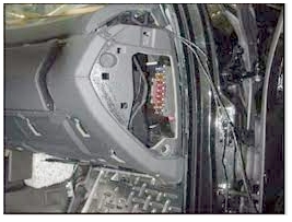
Fuse box diagram in the instrument panel on the right
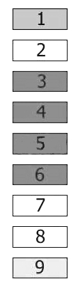
Description
- 7.5A Steering Column Control Module, Engine Control Module, EIS Control Module, Alarm
- 5A Instrument panel
- 10A Top Control Panel Module
- 10A Diagnostic Link Connector (DLC)
- 10A Climate control, Air conditioning control unit
- 10A Center console
- 5A Diagnostic Link Connector (DLC)
- 5A Instrument panel
- 15A Cigarette Lighter Fuse (Front), Ashtray Light
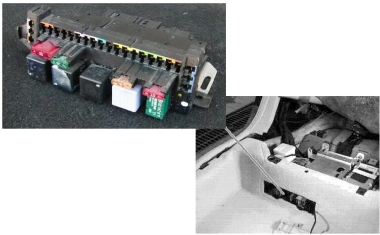
Mercedes w220 rear seat fuse box and relay diagram
Description
| 1 | 10A Rear Window Curtain Relay |
| 2 | 5A Slip Sensor |
| 3 | 30A Fuel Pump Relay |
| Additional relay, fuel pump | |
| 4 | 50A Rear Window Defogger Relay |
| 5 | 10A Trailer Control Unit |
| 6 | 25A Trailer Socket |
| 7 | 30A Trailer Control Unit |
| 8 | 25A Closing the luggage compartment |
| Trunk lid release relay | |
| 9 | 7.5A Keyless Go Control Unit |
| 10 | 30A Control unit (for taxi) |
| 11 | Reserve |
| 12 | 15A Voice Control Unit |
| Hands-free phone | |
| 13 | 20A Pneumatic System Equipment (PSE) |
| 14 | 7.5A Telephone |
| 15 | 7.5A Multifunctional Control Unit |
| Antenna amplifier | |
| 16 | Reserve |
| 17 | 25A Audio Amplifier |
| 18 | 25A Electric rear seats |
| 19 | 15A Rear Air Conditioner |
| Coolant circulation pump | |
| 20 | 15A Rear Air Conditioner |
| 21 | 10A Tire Pressure Monitoring System Control Unit |
| 22 | 25A Front Left Seat Belt Pretensioner |
| 23 | 40A Door control unit, rear left |
| 24 | 25A Front Right Seat Belt Pretensioner |
| 25 | 40A Door control unit, rear right |
| 26 | 10A Parking sensors |
| 27 | 15A Refrigerator (in the back of the rear seat) |
| 28 | 40A Overhead console (in ceiling) |
| R1 | Rear Window Curtain Relay |
| R2 | Slip Sensor Relay |
| R3 | Terminal 15 of the relay |
| R4 | Fuel pump relay |
| Additional relay, fuel pump | |
| R5 | Rear window heating relay |