The compact Nissan Micra is a European copy of the Japanese version of the Nissan March . It has been produced since 1982. Currently, the 7th generation is in production. The first has the body marking K10, the second – K11, the third – K12, etc. In our material you can find a description of the fuse blocks and relays of the Nissan Micra for the second (K11) and third (K12) generations, which were produced in 1992, 1993, 1994, 1995, 1996, 1997, 1998, 1992, 0 , 2004, 2005, 2006, 2007, 2008, 2009 and 2010, as well as their diagrams and a description of the purpose of the elements. We note the fuses that are responsible for the cigarette lighter.

Description for K12
General location
Scheme
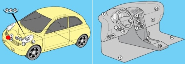
Appointment
| 1 | Air conditioning control unit – behind the heater control panel |
| 2 | Sunlight sensor (air conditioning system) |
| 3 | Intake air temperature sensor (air conditioner/heater) |
| 4 | Impact sensor (SRS) |
| 5 | Impact sensor, driver’s side – under the seat |
| 6 | Impact sensor, passenger side – under the seat |
| 7 | Anti-theft system control unit – if installed |
| 8 | Rechargeable battery |
| 9 | Central locking relay – “keyless entry”, if available |
| 10 | Diagnostic Connector (DLC) |
| 11 | Coolant heater relay. |
| 12 | Fuse and relay block, engine compartment 1 |
| 13 | Fuse and relay block, engine compartment 2 |
| 14 | Fuse and relay block, engine compartment C |
| 15 | Fuse and relay block, engine compartment 4 – diesel engine |
| 16 | Fuse and relay block dashboard |
| 17 | Additional fuse (Main250A) – battery |
| 18 | Heater fan motor resistor – in the heater fan motor |
| 19 | Audible signal – behind the radiator grille |
| 21 | Immobilizer transponder-ignition lock |
| 24 | Multifunction control unit 2 – functions: central locking, electric windows, hazard warning light, rear window heater, immobilizer control unit, turn signals, interior lights, fog light, rear window wiper, windshield washer wiper |
| 25 | Navigation system control unit – in the audio system unit (if equipped) |
| 26 | Ambient air temperature sensor |
| 27 | Start-inhibit switch – on the gearbox |
| 28 | Power steering control unit |
| 29 | SRS electronic control unit |
| 30 | Electronic gearbox control unit |
| 31 | Trip computer |
Fuses in the passenger compartment
It is located in the instrument panel next to the steering rack. This unit is covered by a protective cover, on the back of which there will be a current description.
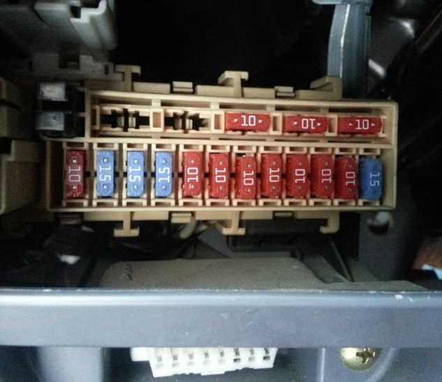
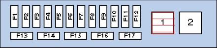
Marking
| 1 | Auxiliary equipment relay |
| 2 | Heater fan motor relay |
| F1 | (15A) Windshield wiper |
| F2 | (10A) Instrument cluster indicators |
| F3 | (10A) SRS system |
| F4 | (10A) Multifunction control unit 1, diagnostic connector |
| F5 | (10A) Brake light switch (brake pedal position sensor), ABS system, brake lights |
| F6 | (10A) Central locking, anti-theft system, air conditioning system |
| F7 | (10A) Multifunction control unit 1 |
| F8 | (10A) Instrument cluster indicators, diagnostic connector (DLC) |
| F9 | (15A) Heater air conditioner |
| F10 | (15A) Heater air conditioner |
| F11 | (15A) Cigarette lighter fuse nissan micro |
| F12 | (10A) Audio system, navigation system, anti-theft system, electric door mirrors, trip computer |
| F13 | (10A) Rear window heater |
| F14 | (10A) Daytime running light bulbs |
| F15 | (10A) Seat heater |
| F16 | (10A) Air conditioner |
| F17 | (10A) Anti-theft system, central locking, interior lights |
Fuse number 11 at 15A is responsible for the cigarette lighter.
Fuses under the hood
Relay block behind the headlight
Photo
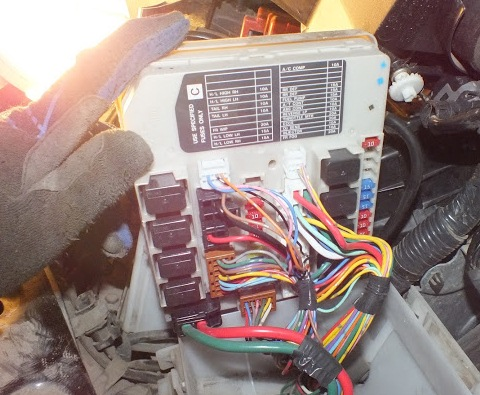
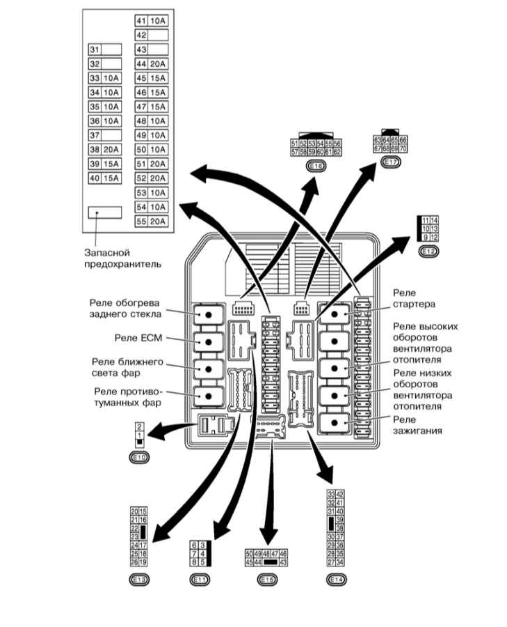
Decoding fuses
| F31 | – |
| F32 | – |
| F33 | (10A) Right headlight – high beam, daytime running light system – if equipped |
| F34 | (10A) Left high beam headlight, daytime running light system – if equipped |
| F35 | (10A) Rear right side marker |
| F36 | (10A) Rear left side marker |
| F37 | – |
| F38 | (20A) Windshield wiper |
| F39 | (15A) Low beam headlight, daytime running light system — if equipped |
| F40 | (15A) Low beam – right headlight, daytime running light system – if available, headlight range control |
| F41 | (10A) Air conditioner relay |
| F42 | – |
| F43 | – |
| F44 | – |
| F45 | (15A) Rear window defroster relay |
| F46 | (15A) Rear window defroster relay |
| F47 | (15A) Fuel pump relay |
| F48 | (10A) Electronic gearbox control unit |
| F49 | (10A) Anti-lock braking system (ABS) |
| F50 | (10A) Start-inhibit switch |
| F51 | (20A) Throttle control unit relay |
| F52 | (20A) Engine control |
| F53 | (10A) Heated oxygen sensors |
| F54 | (10A) Injectors |
| F55 | (20A) Fog lights |
Additional blocks
Block 1
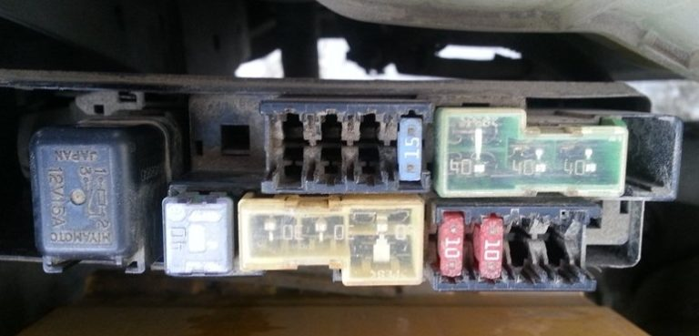
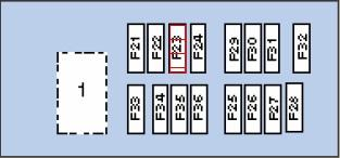
Appointment
| 1 | Horn relay |
| F21 | – |
| F22 | – |
| F23 | – |
| F24 | (15A) Audio system, navigation system |
| F25 | (10A) Sound signal |
| F26 | (10A) Generator |
| F27 | (10A) Daytime lighting system – if available |
| F28 | (10A) – |
| F29 | (40A) ABS electronic control unit |
| F30 | (40A) Cooling system fan motor relay |
| F31 | (40A) Ignition switch |
| F32 | (40A) Coolant heater |
| F33 | (40A) Multifunction control unit 1 |
| F34 | (30A) ABS electronic control unit |
| F35 | (30A) Headlight Washer Pump Relay |
| F36 | (60A) ABS electronic control unit |
Block 2
High power fuse block diagram
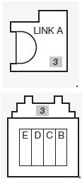
Marking
- A – 250A Main fuse
- B – 80A ABS electronic control unit
- C – 80A Multifunction control unit 1
- D – 60A Fuse/Relay Block – Engine Compartment 1 (F45-F46), (F51-F52), Ignition Main Circuit Relay
- E – 80A Fuse/Relay Block – Instrument Panel (F5-F8), (F14), (F17), Auxiliary Relay, Heater Fan Motor Relay
Description for K11
General location
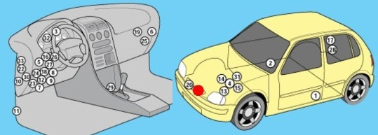
Marking
| 1 | Side impact sensor (SRS system), driver’s side |
| 2 | Side impact sensor (SRS system), passenger side |
| 3 | Audible warning signal / buzzer – instrument cluster |
| 4 | Rechargeable battery |
| 5 | Central locking control unit |
| 6 | Central locking system signal control unit |
| 7 | Diagnostic Connector (DLC), 14-pin |
| 8 | Diagnostic connector, 16-pin |
| 9 | Daytime lighting system control unit – if available |
| 10 | Fog light relay |
| 11 | Fuel pump relay – right lower protective panel |
| 12 | Fuse/relay block instrument panel |
| 13 | Fuse/relay block, engine compartment 1 |
| 14 | Fuse/Relay Block, Engine Compartment 2 – Petrol |
| 15 | Fuse/Relay Block, Engine Compartment 3 – Diesel |
| 16 | Headlight washer delay relay – if equipped |
| 17 | Rear window heater relay, if there is a rear pillar |
| 18 | Heater fan motor relay |
| 19 | Heater fan motor resistor |
| 20 | Sound signal 1 |
| 21 | Beep 2 |
| 22 | Horn relay |
| 23 | Auxiliary ignition circuit relay |
| 24 | Main ignition circuit relay |
| 25 | Electronic immobilizer control unit |
| 26 | Turn signal interrupter relay |
| 27 | Rear window wiper motor relay – rear pillar |
| 28 | SRS electronic control unit |
| 29 | Electronic gearbox control unit |
| 30 | Vehicle speed sensor, type 1 — gearbox |
| 31 | Vehicle speed sensor, type 2 – instrument cluster |
| 32 | Windshield wiper motor relay |
Fuses in the passenger compartment
Located on the instrument panel.
Option 1
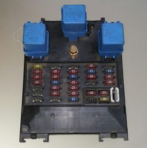
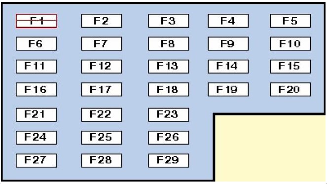
Description
| F1 | (20 A) Air conditioner fan motor – heater |
| F2 | – |
| F3 | (10A/ 20A) Rear window defroster switch, rear window defroster relay |
| F4 | (10A) Horn relay |
| F5 | (15A) Fog light relay |
| F6 | (10A) Air conditioning system, start-inhibit switch |
| F7 | (7.5A) Central locking, Idle Speed Control (ISC) relay – with automatic transmission, diagnostic connector |
| F8 | (10A) Rear window defroster relay – if equipped, central locking, central locking signal control unit, daytime running light control unit – if equipped, start prevention switch (PVN), reversing lights |
| F9 | (15A) Rear window washer cleaner |
| F10 | (15A) Audio system |
| F11 | (7.5A) Hazard warning switch |
| F12 | (7.5A) ABS electronic control unit |
| F13 | (15A) Cigarette lighter fuse |
| F14 | (10A) Brake lights, ABS |
| F15 | (10A) Hazard warning switch |
| F16 | (10A) Electronic gearbox control unit |
| F17 | (15A) Fuel pump relay |
| F18 | (10A) Seat heater |
| F19 | (20A) Windshield wiper motor, windshield wiper motor relay |
| F20 | (7.5A) Engine management system, immobilizer control unit |
| F21 | – |
| F22 | (10A) SRS electronic control unit |
| F23 | (10A) Windshield washer fluid |
| F24 | (10A) Fuel shut-off valve electronic control unit – Diesel, interior lights, instrument cluster, audio system, electronic gearbox control unit, immobilizer, central locking signal control unit |
| F25 | (10A) Glow Plug Control Module – Diesel, EGR Valve or EGR – Diesel, Immobilizer, Heated Oxygen Sensor, Idle Air Control Valve |
| F26 | (7.5A) Immobilizer switch relay – with automatic transmission, engine management system |
| F27 | – |
| F28 | – |
| F29 | (15A) Headlight washer delay relay |
Fuse number 13 at 15A is responsible for the cigarette lighter.
Option 2
Photo
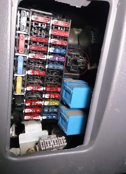
Compare the diagram with your description on the back of the cover.
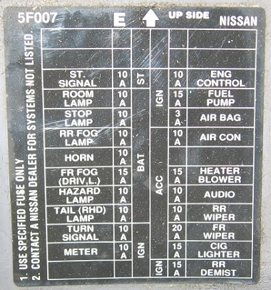
Marking
- 10A Starter/signal
- 10A Interior lighting
- 10A Stop signal lamp
- 10A Fog lights
- 10A Signal
- 15A Fog lights
- 10A Emergency alarm
- 10A Rear lights
- 10A Turn signals
- 10A Instrument panel
- 10A Engine
- 15A Fuel pump
- 3A Fuel pump
- 10A Air conditioner
- 15A Heater fan
- 10A Audio system
- 10A Rear wiper
- 20A Front windshield wiper
- 10A Cigarette lighter
- 10A Fog lights
In this version, the second fuse from the bottom in the right column at 15A is responsible for the cigarette lighter. In the diagrams, it is marked as CIG LIGHTER.
Fuses under the hood
Option 1
Photo
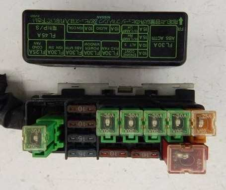
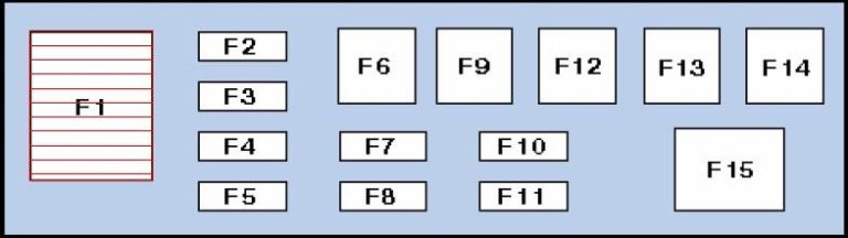
Transcript
| F1 | (30A) Glow plug control unit – diesel |
| F2 | – |
| F3 | (10A) Rear dimensions |
| F4 | (15A) Right headlight |
| F5 | (15A) Left headlight |
| F6 | (25A) Power window actuator, central locking control unit |
| F7 | (15A) Spare |
| F8 | – |
| F9 | (25A) Cooling system fan motor |
| F10 | (10A) Spare |
| F11 | (15A) Air conditioner |
| F12 | (30A) Anti-lock braking system (ABS) |
| F13 | (30A) Ignition switch |
| F14 | (25A) Engine control |
| F15 | (65A) Battery power distribution |
Option 2
Photo
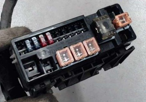
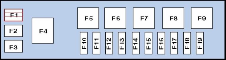
Appointment
| F1 | (40A) ABS electronic control unit |
| F2 | (30A) Ignition switch |
| F3 | (40A) ABS electronic control unit |
| F4 | (80A) Battery power distribution |
| F5 | (30A) Cooling system fan motor |
| F6 | (30A) Electric window lifter, central locking control unit |
| F7 | (30A) Engine control |
| F8 | – |
| F9 | (60A) Glow plug control unit – diesel |
| F10 | – |
| F11 | – |
| F12 | – |
| F13 | – |
| F14 | – |
| F15 | (10A) Generator |
| F16 | (10A) Rear dimensions |
| F17 | (15A) Left headlight |
| F18 | (15A) Right headlight |
| F19 | (15A) Air conditioner |