Volkswagen Sharan has been supplied to the markets from 1995 to the present in two generations. The 1st generation was produced in 1996, 1997, 1998, 1999, 2000, 2001, 2002, 2003, 2004, 2005, 2006, 2007, 2008 and 2009. During this time, the car was restyling twice. Accordingly, the block execution schemes, as well as several. In this material, we will show the location of all electronic control units, describe in detail the purpose of fuses and relays in the Volkswagen Sharan 1st generation. Separately, we will note the cigarette lighter fuse.
The number of blocks, their design and purpose of the elements may differ from the one presented and depends on the year of manufacture, equipment level and country of delivery. We will present the two most popular options: the first option is suitable mainly for models manufactured before 1998, and the second after.
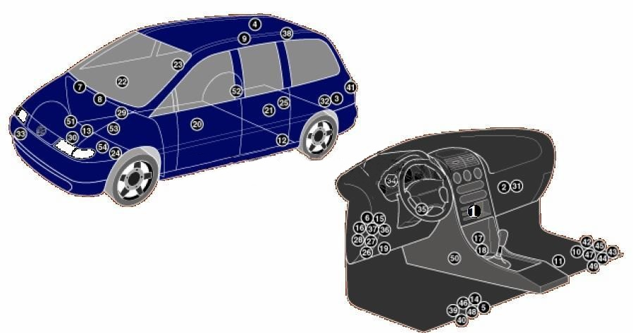
Description
| 1 | Electronic air conditioning control unit |
| 2 | Air conditioner heater fan motor control unit, front (with automatic temperature control) |
| 3 | Air conditioner heater fan motor control unit, rear (with automatic temperature control) |
| 4 | Antenna signal amplifier – behind the ceiling |
| 5 | Anti-theft system control unit central locking control unit – under the driver’s seat (^08/97) |
| 6 | Anti-theft system control unit – in the multifunction control unit (09/97^) |
| 7 | Anti-theft alarm – intake system resonator (^04/00) |
| 8 | Anti-theft alarm – intake system resonator (05/00^) |
| 9 | Audio antenna – right rear side window |
| 10 | Additional battery under passenger seat, if available |
| 11 | Auxiliary battery relay (11/98) – under the front right seat |
| 12 | Auxiliary heater control unit |
| 13 | Rechargeable battery |
| 14 | Central locking control unit – in the anti-theft system control unit – under the driver’s seat (^08/97) |
| 15 | Central locking control unit – in the multifunction control unit (09/97) |
| 16 | Control unit (in case of emergency) – fuse/relay unit 2 of the instrument panel |
| 17 | Cruise control system control unit |
| 18 | Diagnostic Connector (DLC) – ^04/00 – under the front ashtray |
| 19 | Diagnostic Connector (DLC) – 05/00 ^ |
| 20 | Left front window control unit – door |
| 21 | Left rear window control unit – door |
| 22 | Right front window control unit – door |
| 23 | Right rear window control unit – door |
| 24 | Cooling system fan motor control unit |
| 25 | 4WD electronic control unit – on the clutch |
| 26 | Fuse/relay block, instrument panel 1 – in multifunction control unit (09/97^) |
| 27 | Fuse/relay block instrument panel 2 |
| 28 | Fuse/relay block instrument panel 3 |
| 29 | Fuse/relay block, engine compartment 1 |
| 30 | Fuse/relay block, engine compartment 2 |
| 31 | Heater fan motor resistor, front (manual temperature control) |
| 32 | Heater fan motor resistor, rear (manual temperature control) |
| 33 | Horns – behind the bumper |
| 34 | Immobilizer control unit – by instrument cluster |
| 35 | Immobilizer ring antenna – near the ignition switch |
| 36 | Turn signal relay – in the multifunction control unit |
| 37 | Multifunction control unit – in the fuse/relay block of the dashboard 1 – functions: windshield heater/rear window heater, windshield wipers/rear window wiper, turn signals, hazard warning lights, interior lights, power windows, central locking, anti-theft system |
| 38 | Navigation system antenna, telephone |
| 39 | Parking system control unit – under the driver’s seat |
| 40 | Parking system buzzer, front – under the driver’s seat |
| 41 | Parking system buzzer, rear – under the rear position lamp cover |
| 42 | Additional fuse (30A/40A), battery – under the front right seat |
| 43 | Additional fuse (30A), additional heater (09/01) – under the front right seat |
| 44 | Additional fuse (15A), accessory power connector 1 (1/98 – 05/00) – under the front right seat |
| 45 | Additional fuse (15A), accessory power connector 2 (1/98 – 05/00) – under the front right seat |
| 46 | Seat heating control unit, driver’s side – under the driver’s seat |
| 47 | Seat heating control unit, passenger side – under the passenger seat |
| 48 | Side impact sensor, driver’s side – under the driver’s seat |
| 49 | Side impact sensor, passenger side – under the passenger seat |
| 50 | SRS electronic control unit |
| 51 | Body height sensor, front – headlight leveling on anti-roll bar |
| 52 | Body height sensor, rear headlight corrector – rear right axle shaft |
| 53 | Electronic transmission control unit – engine compartment, left |
| 54 | Car speed sensor – on the gearbox |
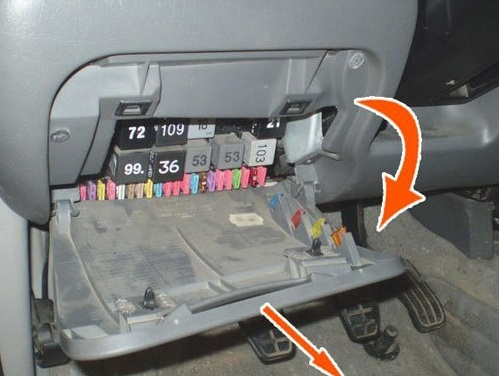
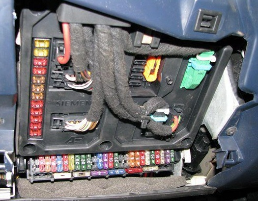
Fuse and relay blocks in the passenger compartment
The main fuse and relay blocks are located on the left side of the instrument panel, behind a protective cover.
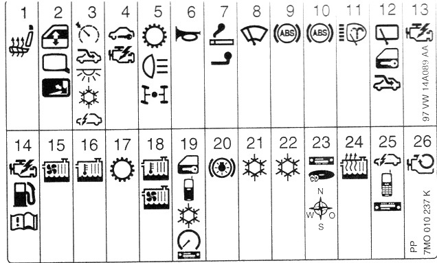
Fuse block
Option 1
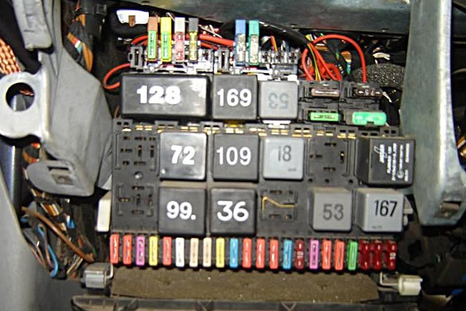
Description
| 1 | – |
| 2 | (72) Rear window washer wiper relay |
| 3 | (30/109) Engine control system relay – ADY /AKT /1Z /AHU /AFN |
| 4 | (18) Ignition auxiliary circuit relay |
| 5 | – |
| 6 | (21/22) Alarm relay |
| 7 | (95) Headlight washer pump relay |
| 8 | (19/99) Windshield washer intermittent relay |
| 9 | (36) Headlight warning buzzer |
| 10 | (53) Fog light relay |
| 11 | (53) Horn relay |
| 12 | (167) Fuel Pump Relay – AAA/ADY/AKT |
| 13 | (128) Traffic light switching relay |
| 14 | (169) Rear window heater relay |
| 15 | (53/204) Windshield wiper motor relay |
| F1 | (10A) Left headlight – low beam, headlight leveling control – left |
| F2 | (10A) Right headlight – low beam, right headlight leveling control |
| F3 | (3A) License plate lights |
| F4 | (20A) Rear window washer, daytime running lights, air conditioning/heater fan motor – rear |
| F5 | (10A) Windshield washer cleaner, windshield washer nozzle heaters |
| F6 | (25A) Air conditioning system, air conditioning/heater fan motor |
| F7 | (5A) Front/rear marker light (right), engine compartment light |
| F8 | (5A) Front left side marker / rear left side marker lamps |
| F9 | (20A) Rear window defroster, windshield defroster relay |
| F10 | (15A) Rear fog lights |
| F11 | (10A) Left headlight |
| F12 | (10A) Right headlight |
| F13 | (10A) Audible signal |
| F14 | (15A) Reversing light(s), cruise control, windshield defroster relay, central locking, power windows, power door mirrors, seat heater, air conditioning, auxiliary heater, all-wheel drive system, automatic transmission, automatic transmission selector light |
| F15 | (5A/10A) Engine management system, immobilizer, gear selector light, crankcase ventilation breather heater, EGR valve, fuel vapor accumulator valve |
| F16 | (3A) Clock, interior light bulb — front, glove box light bulb, rear window heater relay, instrument cluster |
| F17 | (10A)Turn signals |
| F18 | (10A) Fuel pump, heated oxygen sensor – AAA/ ADY /AKT |
| F19 | (30A) Cooling system fan motor control unit, cooling system fan motor |
| F20 | (10A) Brake light switch (brake pedal position sensor) |
| F21 | (10A) Instrument cluster, clock, audio system, audio system CD changer, audio system output amplifier, interior lights, sunroof |
| F22 | (10A) Air Conditioning System, Diagnostic Link Connector (DLC) |
| F23 | (7.5A) Cooling system fan motor control unit, coolant pump motor, air conditioning compressor electromagnetic clutch |
| F24 | (30A) Windshield wiper |
| F25 | (60A) Glow plugs |
| F26 | Reserve |
| F27 | (50A) Windshield heater |
| F28 | (30A) ABS electronic control unit |
| F29 | (30A) ABS electronic control unit |
| F30 | (10A) Central locking |
| F31 | (10A) Central locking, anti-theft alarm |
| F32 | (10A) Central locking, hazard warning lights-anti-theft system |
| F33 | (25A/30A) Auxiliary heater |
| F34 | (25A) Air conditioner/heater fan motor – rear |
| F35 | (20A) Cigarette lighter, trailer electrical connector, accessory power connector |
| F36 | (10A) Telephone |
| F37 | (30A) Electric window regulator |
| F38 | (20A) Spare |
| F39 | (25A) Front Climatronic module |
| F40 | (5A) Cooling system fan motor relay 1 and 2 speed |
In this version, fuse number 35 at 20A is responsible for the cigarette lighter, and fuse number 22 is responsible for the additional sockets.
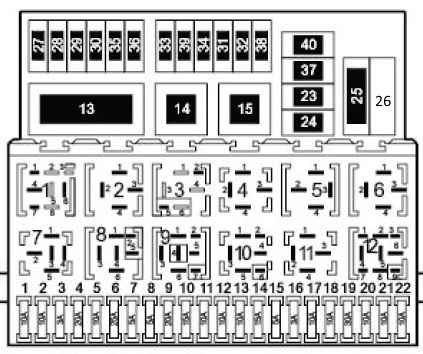
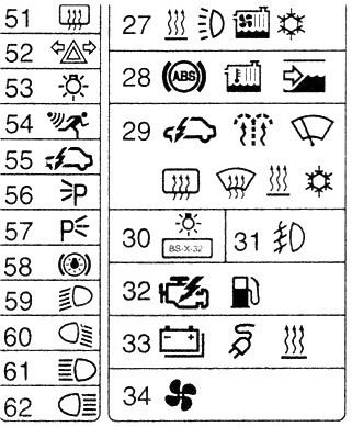
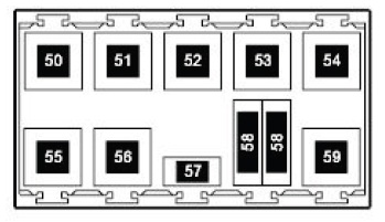
Option 2
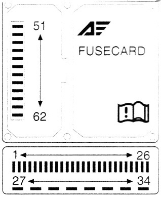
The actual purpose may be presented in the form of a brochure located on the back of the protective cover.
Numbered diagram
Detailed purpose
| 1 | (20A) Seat heater |
| 2 | (10A) Power window actuator, power door mirrors actuator |
| 3 | (5) Cruise control, sunroof, glove box light, clock, navigation system, air conditioning system, auxiliary heater, multifunction unit/dashboard |
| 4 | (10A) Engine management, immobilizer, crankcase ventilation breather heater-AAA/AMY/ANU |
| 5 | (15A) Reversing lamp(s), automatic transmission (ATC), all-wheel drive system |
| 6 | (10A/25A) Audible signal |
| 7 | (20A) Cigarette lighter |
| 8 | (30A) Windshield wiper/washer |
| 9 | (30A) Anti-lock braking system (ABS) |
| 10 | (30A) Anti-lock braking system (ABS) |
| 11 | (20A) Headlight washers |
| 12 | (15A) Sunroof, clock, multifunction control unit: Central locking, rear window wiper/washer |
| 13 | (3A) Engine control-gasoline |
| 14 | (10A/20A/25A/30A) motor control |
| 15 | (30A) Cooling system fan motor -AAA/AFN/AHU |
| 16 | (15A/30A) Cooling system fan motor (06/00^) |
| 17 | (10A) Automatic transmission |
| 18 | (5A/10A) Cooling system fan motor |
| 19 | (5A) Central locking, telephone, air conditioning system, instrument cluster, audio system, parking system (11/98-05/00), diagnostic connector (DLC) |
| 20 | (10A) Stop signals |
| 21 | (25A/30A) air conditioner |
| 22 | (25A/30A) air conditioner |
| 23 | (10A) Audio system, audio CD changer, navigation system |
| 24 | (25A) Auxiliary heater |
| 25 | (3A) Multifunction control unit, telephone, audio system |
| 26 | (30A) Immobilizer switch relay/reverse light relay |
| 27 | (25A) Air conditioning system, cooling system fan motor |
| 28 | (10A) Anti-lock braking system (ABS), cooling fan motor, windshield wiper/washer |
| 29 | (5A) Multifunction control unit, windshield washer nozzle heaters, windshield wiper (—^10/98), windshield heater, rear window heater, auxiliary heater, ventilation heating system (—10/98), air conditioning |
| 30 | (3A) License plate lights |
| 31 | (15A) Fog lights |
| 32 | (3A/10A) Engine control-ADY /AAAAJ H/AKT /ANU |
| 33 | (25A) Trailer electrical connector, accessory power connector (12v), additional battery |
| 34 | (25A) Heating/ventilation system |
| 51 | (20A) Rear window heater |
| 52 | (20A) Turn signals |
| 53 | (10A) Interior lights |
| 54 | (10A) Anti-theft system |
| 55 | (5A) Door opening lights, instrument cluster, anti-theft system, central locking, power windows |
| 56 | (5A) Front right side marker lamps, rear right side marker lamps |
| 57 | (5A) Front left side marker lamps, rear left side marker lamps |
| 58 | (10A) Headlight leveler |
| 59 | (10A/15A) Left headlight – low beam |
| 60 | (10A/15A) Right headlight – low beam |
| 61 | (10A) Left headlight – high beam |
| 62 | (10A) Right headlight – high beam |
In this version, fuse number 7 at 20A is responsible for the cigarette lighter, and fuse number 8 is responsible for additional sockets.
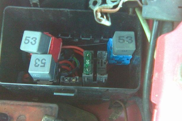
Relay blocks
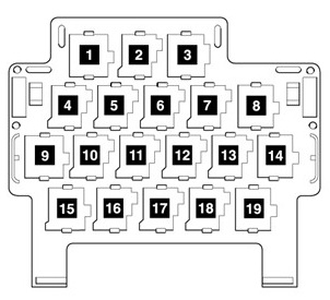
Option 1
Main unit
Scheme
Decoding the elements
- 1 Diagnostics splitter
- 2 Splitter Terminals 15a
- 3 Branching device Terminal 58b
- 4 Speed signal splitter
- 5 Branching device Terminal 54
- 6 Door limit switch splitter
- 18 – Radio-telephone speaker switching relay
- 19 – Daytime Running Light Relay (200)
- Reserve
- 31 – Rear vented window relay (149)
- 22 – Windshield heating relay (170)
- 23 – Not used
- 24 – Electric window lifter relay (53)
- 25 – Rear heater supply fan relay (94)
- 26 – Seat belt warning relay
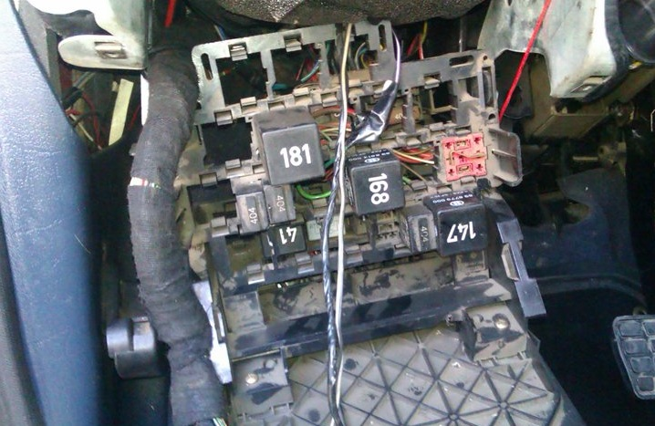
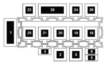
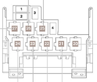
Option 2
Main unit
Scheme
Marking
| 1 | (361) Mirror folding control unit |
| 2 | (361) Mirror folding control unit |
| 3 | Relay that switches the audio system/telephone speaker |
| 4 | (94) Heater fan motor relay – without air conditioning |
| 5 | (53/131/181) Cooling system fan motor cut-off relay (after engine stop) |
| 6 | (175) Immobilizer switch relay/reverse light relay |
| 7 | (106) Auxiliary heater relay (^04/98) |
| 8 | (95) Headlight washer pump relay |
| 9 | (200) Daytime running light relay – if installed |
| 10 | (53/404) Horn relay |
| 11 | (94) Air Conditioner Compressor Electromagnetic Clutch Relay – AFN/AHU |
| 12 | (168) Air conditioner compressor electromagnetic clutch relay |
| 13 | (153) Diode |
| 14 | (185) Immobilizer relay |
| 15 | (114) Heater fan motor relay – additional heater (^04/98) |
| 16 | (149) Rear side window power relay |
| 17 | (53/404) Auxiliary heater relay |
| 18 | (94) Coolant pump relay |
| 19 | (109) Engine control system relay |
Additional unit
Purpose of elements
- 50A – Heated windshield
- 50A – Secondary air pump, 25A – Additional heater
- 25A – Additional heater
- 30A – Separate fuse for glass – lifts
| 20 | (404) Auxiliary heater operation relay |
| 21 | (53) Windshield wiper motor relay / radiator fan relay (361) |
| 22 | (53) Exhaust air pump relay / exterior mirror heating relay (404) |
| 23 | (100) Windshield defroster relay |
| 24 | (167) Fuel pump/fan relay (53) |
| 25 | (53) Coolant heater relay |
| 26 | (100) Ignition auxiliary circuit relay |
| 27 | (114) Air conditioner compressor electromagnetic clutch disconnection relay |
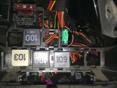
Fuse and relay blocks under the hood
The main power fuse block is located next to the battery and is covered by a cover.
Main unit
Photo – diagram
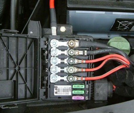
Transcript
- 60A – Glow plugs
- 40A – Radiator fan
- 40/60A – Radiator fan
- 110A – Interior of the cabin
- 150A – Generator
- 3A – Multifunctional control unit
- 30A – ABS
- 30A – ABS (pump)
On some models, another additional unit was installed
Additional unit
Description
- 50 – Air conditioner disconnect relay (114)
- 51 – Air conditioner off relay (147)
- 52 – Reserve
- 53 – Reserve
- 54 – High power heating relay (103)
- 55 – Starter and reversing light relay (158)
- 56 – Air pump relay (53)
- 57 – Secondary air pump relay
- 58 – Radiator fan fuse, glow plugs for additional coolant heating elements
- 59 – Low heating power relay (103)