The Hyundai i20 subcompact hatchback has been produced from 2008 to the present in 2 generations. The first generation was produced in 2009, 2010, 2011, 2012, 2013 and 2014. During this time, the model has undergone restyling. Since 2015, the second generation of the Hyundai i20 has been on sale. In this material you will find a description of the fuses and relays of the Hyundai i20 with block diagrams and their locations. We note the cigarette lighter fuse.

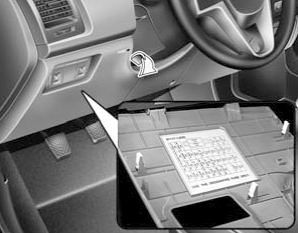
Cabin block
Located at the bottom of the instrument panel.
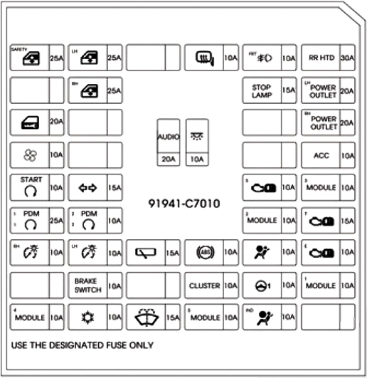
Example of a scheme. Option 1.

example of a scheme. Option 2.
Description
| P/WDW-LH | Main switch for electric windows, automatic locking unit for the driver’s door electric window, right rear door power window control switch, front passenger door power window control switch (for right-hand drive vehicles) |
| S/HTD | Front passenger seat heating switch, driver seat heating switch |
| RR WIPER | Rear window wiper motor, multifunction switch (wiper control switch) |
| H/LP RH | Right headlight, instrument panel (headlights on) |
| IGN 2 | Headlight range control switch, interior air temperature sensor, body control module (BCM), air conditioning control module, sunroof control module, left/right headlights, engine compartment fuse and relay block (fuel filter heater relay (FFHS)), daytime running light relay (DRL), fan relay), diesel engine fuse and relay block (PTC heater relay 2, PTC heater relay 3) |
| PCU | Fuel filter warning sensor, air flow sensor, engine control module (ECM) (if equipped with manual transmission), powertrain control module (PCM) (if equipped with automatic transmission) |
| STOP LP | Brake light switch, data link connector (DLC), power window relay |
| A/BAG | Seat belt unfastened sensor module, SRS electronic control unit |
| HAZARD | Hazard warning switch, hazard warning relay |
| SAFETY P/W | Automatic locking unit for the driver’s door electric window lifter |
| CLUSTER | Trip computer, instrument panel (lighting), body control module (BCM) |
| TCU | Overdrive switch, pulse generator “A”, pulse generator “B”, vehicle speed sensor |
| IGN1 | Generator (KAPPA), electric power steering system control unit (EPS), tire pressure monitoring unit |
| ABS | Electronic Stability Program (ESP) switch, steering angle sensor, anti-lock braking system (ABS) control unit, ESP control unit, yaw rate sensor, engine compartment fuse and relay block (multi-purpose control connector) |
| IGN COIL | Ignition coil (KAPA), ignition coils No. 1 – 4 (GAMA), condenser (GAMA) |
| B/UP LP | Transmission mode switch (GAMMA), reverse lamp switch |
| A/BAG IND | Instrument panel (airbag lighting) |
| T/SIG LP | Emergency alarm switch |
| TAIL LP LH | Daytime running light (DRL) relay, license plate lamp, left rear combination lamp, left headlight |
| TAIL LP RH | Right headlight, right rear combination lamp, lighting |
| ACC | Electric exterior mirrors, audio system, on-board computer |
| C/LIGHT | Cigarette lighter |
| RR FOG LP | Rear fog light relay |
| B/A HORN | Anti-theft alarm relay |
| DR LOCK | Tailgate unlock relay, door lock relay, door full lock relay |
| FRT FOG LP | Front fog light relay |
| FOLDING | Power door mirror control switch |
| S/ROOF | Sunroof control unit |
| START | Engine Control Module (ECM) (for diesel vehicles), engine compartment fuse and relay block (starter relay, anti-theft alarm relay) |
The cigarette lighter fuse is marked as C/LIGHT or POWER OUTLET on the diagram.
Blocks under the hood
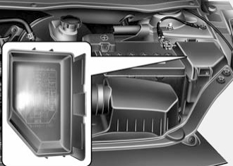
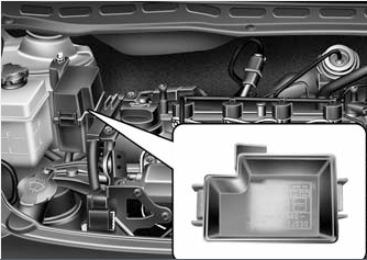
Main unit
Located in the left side of the engine compartment, next to the battery.
Option 1
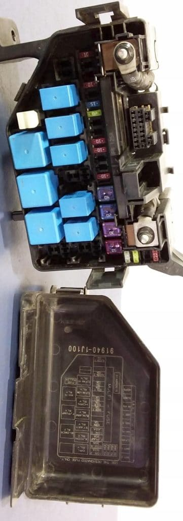
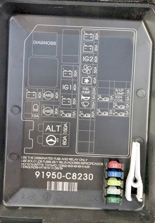
Appointment
| JSC 2 | Dashboard junction box (power window relay, fuses (SAFETY P/W – 15 A, HAZARD – 15 A)) |
| OJSC 1 | Dashboard junction box (rear light relay, fuses (S/ROOF – 20 A, FOLDING – 10 A, DR LOCK – 20 A, STOP LP – 15 A, B/A HORN – 15 A, RR FOG LP – 10 A , FRT FOG LP – 10 A, power connector (ROOM – 10 A, AUDIO – 20 A)) |
| C/FAN | Cooling fan high speed relay, cooling fan low speed relay. |
| MAIN | Generator, fuses (ABS 1 – 40 A. ABS 2 – 40 A, RR HTD – 40 A, BLOWER – 40 A, MDPS – 80 A, A/CON 1 – 10 A) |
| ABS2 | Multi-purpose control connector, anti-lock braking system (ABS) control unit, electronic stability program (ESP) control unit |
| ABS 1 | Multi-purpose control connector, anti-lock braking system (ABS) control unit, electronic stability program (ESP) control unit |
| RR HTD | Rear heating relay |
| BLOWER | Fan relay |
| MDPS | Electronic Stability Program (ESP) control unit |
| IGN 2 | Ignition |
| ECU A | Engine control unit (ECM) (if equipped with a manual transmission), transmission control unit (PCM) (if equipped with an automatic transmission), engine control relay (main relay) |
| F/PUMP | Fuel pump relay |
| IGN 1 | Ignition switch |
| HORN | Horn relay |
| SNSR 1 | Camshaft position sensor, fuel vapor storage purge solenoid valve, oxygen sensor (upstream, downstream), immobilizer control unit, low speed cooling fan relay, high speed cooling fan relay |
| ECU B | Engine control unit (ECM) (if equipped with a manual transmission), transmission control unit (PCM) (if equipped with an automatic transmission) |
| DRL | Grounding (Body Electronic Systems Control Unit (BEC)) |
| ECU 1 | Engine control unit (ECM) (if equipped with a manual transmission), transmission control unit (PCM) (if equipped with an automatic transmission) |
| INJ | Injectors 1-4, idle speed control actuator, air conditioning relay, oil flow control valve (GAMMA) |
| A/CON2 | Air conditioning control unit |
| A/CON 1 | Air conditioner relay |
Additional unit
Installed on the right side of the engine compartment on i20 models with diesel engines.
There may be elements responsible for the operation of the engine, such as:
- GLOW – Glow plug relay, air heater relay
- PTC – Auxiliary heater relay