This article provides information about the relay and fuse blocks of the Audi A6 C5 with their diagrams, element designations and box locations. The second generation of the Audi A6 was produced in sedan and station wagon (Avant) bodies in 1997, 1998, 1999, 2000, 2001, 2002, 2003 and 2004, the series was designated as C5.
Arrangement
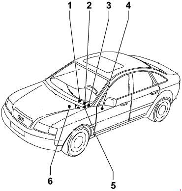
- 3-slot mounting box
- 8-slot mounting box
- Central switchgear with relay box
- Main fuse block
- 13-slot mounting block
- Mounting block in static box
Before replacing a fuse, the relevant load must be disconnected and the ignition must be turned off.
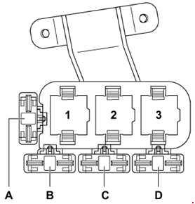
3-slot mounting box
Scheme
Marking
| 1 | Low heat output relay – J359 Brake servo relay – J569 |
| 2 | Auxiliary heater relay – J8Solar isolation relay – J354 |
| 3 | High power relay -J360 |
| A | Not used |
| B | Not used |
| C | Auxiliary heater fuse 2 – S143 Hydraulic pump fuse (brake booster) – S279 Fuel pump fuse – S81 (RS6 LHD) |
| D | Auxiliary heater fuse – S109 Fuel pump fuse – S81 (RS6 RHD) |
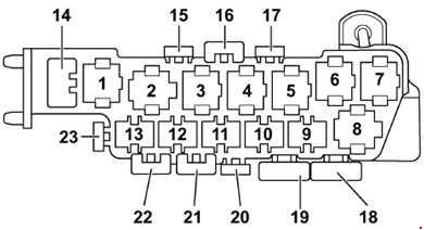
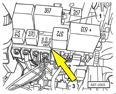
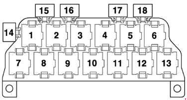
8-slot mounting box
This relay box is located behind the central distribution device. Here is its diagram.
Appointment
| 1 | Relay for solenoid valves – ABS with ESP – J106 |
| 2 | Radiator fan relay (2nd speed) – J101 |
| 3 | Radiator fan relay – J26 Coolant pump relay after engine stop -J151 |
| 4 | Radiator fan switch relay – J138 |
| 5 | Not used |
| 6 | Air suspension compressor relay – J403 (Allroad) |
| 7 | Hydraulic pump relay – ABS with ESP – J105 |
| 8 | Coolant shut-off valve relay – J541 |
| 14 | Driver’s seat adjustment thermal fuse – S44 (Allroad) |
| 15 | Fuse for 12V connector – S184 |
| 16 | Front window thermal fuse – S37 |
| 17 | Rear window thermal fuse – S43 |
| 18 | ABS fuse block – S123 |
| 19 | Radiator fan fuse – S42 |
| 20 | Radiator fan control unit fuse – S142 |
| 21 | Driver’s seat adjustment thermal fuse fuse – S44 Radiator fan fuse – S42 (Allroad) |
| 22 | Air suspension fuse – S110 (Allroad) |
| 24 | Passenger seat adjustment thermal fuse – S80 |
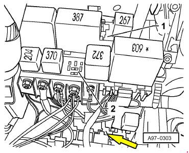
Central switchgear
Scheme
Protected schemes
| 1 | Horn Relay – J4 |
| 2 | Relay contact discharge X – J59 |
| 3 | Low Range Hydraulic Pump Relay – J555 (Allroad) |
| 4 | Fuel Pump Relay – J17 (Gasoline Engines) Glow Plug Relay – J52 (Diesel Engines) |
| 5 | Wiper and Washer Relay – J31 |
| 6 | Wiper and Washer Relay – J31 |
| A | Steering column adjustment fuse – S275 |
| B | Rear curtain fuse – S100 |
| C | Alarm unit fuse II – S181 (taxis) Fuse C – S204 (police cars) Rear emergency exit cover fuse – S195 (special vehicles) Steering wheel multifunction control unit fuse – S326 |
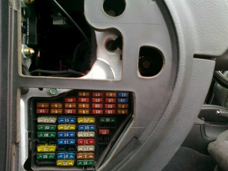
Main fuse block
Located on the left side of the dashboard under a protective cover.
Check the circuit description with the table on the back cover.
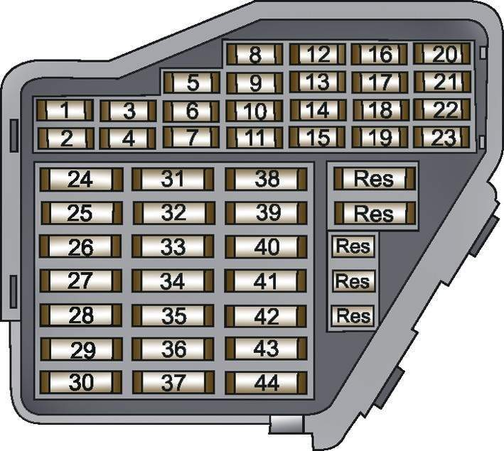
fuse box diagram a6 c5
Protected components
at 10A
| None. | Current consumer | |
| 1 | 5A Heated windshield washer jets, heated exterior mirrors | |
| 2 | 10A Turn signals | |
| 3 | 5A Headlight cleaners, lighting | |
| 4 | 5A License plate light | |
| 5 | 10A Seat heating, lamp control, catalytic converter, light switch, exterior mirror switches and motors, airbag warning light, outside temperature indicator, air conditioning, permanent heating, rear curtain, sunroof, navigation system | |
| 6 | 5A Central locking | |
| 7 | ABS, brake light and clutch pedal control unit | |
| 8 | 5A Telephone, Telematics | |
| 9 | 10A Heated mirrors | |
| 10 | 5A Automatic headlight adjustment | |
| 11 | 10A Cruise control with Multitronic automatic transmission | |
| 12 | 10A Power supply for self-diagnosis system | |
| 13 | 10A Stop signals | |
| 14 | 10A Interior lighting, reading lights, signal lights, sun visor mirror, seat memory | |
| 15 | 10A Instrument cluster, air conditioning, seat and mirror memory, heated clock, navigation system | |
| 16 | 5A Electronic Stability Control | |
| 17 | 10A Navigation system | |
| 18 | 10A Right high beam | |
| 19 | 10A Left high beam | |
| 20 | 10 15A Dipped beam right, headlight control right | |
| 21 | 10 15Ð Low beam left, headlight level control left | |
| 22 | 5A Side and marker lights, right | |
| 23 | 5A Side and marker lights, left | |
| 24 | 25A Wipers, washer pump, time relay | |
| 25 | 30A Ventilation system fan, air conditioning, permanent heating, sunroof | |
| 26 | 30A Heated rear window | |
| 27 | 15A Heated steering wheel | |
| 28 | 20A Fuel pump | |
| 29 | 20/30A Electronic Engine Systems | |
| 30 | 20A Sliding hatch panel | |
| 31 | 15A Reversing lights, cruise control, automatic transmission, auto-dimming interior rearview mirror | |
| 32 | 20A Electronic engine management systems | |
| 33 | 15A Cigarette Lighter FuseAudi A6 C5 | |
| 34 | 15A Electronic engine management systems | |
| 35 | 30A “Plus” continuous trailer power | |
| 36 | 15A Fog lights, rear fog lights | |
| 37 | 20A Telephone, radio | |
| 38 | 20A Trunk lamp, central locking | |
| 39 | 15A Alarm | |
| 40 | 25A Audible signal | |
| 41 | 25A Anti-lock braking system Electronic stabilization system | |
| 42 | 25A Electronic stabilization system | |
| 43 | 5A Contacts S (radio) | |
| 44 | Heated seats 30A |
Fuse No. 33 at 15A is responsible for the cigarette lighter.
13-slot mounting box

Scheme
Marking
| 1 | Horn Relay – J4 ​​(Telematics – USA) |
| 2 | Generator connection relay – J442 Anti-theft alarm control unit – J85 (taxis) Horn relay – J408 (police vehicles) Anti-theft alarm relay, light change – J549 (special vehicles) |
| 3 | Solar battery isolation relay -J309 Anti-theft alarm control unit – J85 (taxis) Horn relay – J408 (police vehicles) Security alarm relay, high level light warning – J461 (special vehicles) |
| 4 | Starter lockout relay -J207 Starter lockout relay and reverse light – J226 |
| 5 | Magnetic clutch relay – J44 Auxiliary heater relay – J8 |
| 6 | Fog light relay – J5 Fuel pump relay – J17 (TDI engines) |
| 7 | Multifunction control unit on the steering wheel – J453 |
| 8 | Multifunction control unit on the steering wheel – J453 |
| 9 | Lamp control unit – J123 |
| 10 | Lamp control unit – J123 |
| 11 | Mirror folding control unit – J351 |
| 12 | Mirror folding control unit – J351 |
| 13 | Servotronic control unit – J236 |
| 14 | Taximeter fuse – S182 Fuse E – S201 (police cars) Hydraulic pump relay fuse – S279 (Allroad) |
| 15 | Not used |
| 16 | Security alarm fuse – S57 (taxis) Fuse B – S202 (police cars) |
| 17 | Taximeter and alarm fuse – S183 (taxis) Fuse C – S203 (police cars) Radio fuse – S253 (emergency vehicles) Fog light fuse – S28 (daytime running lights – Canada) |
| 18 | Installable anywhere Generator connection relay – J442 (special vehicles) Anti-theft alarm control unit II – J430 (taxi) Light alarm relay – J182 (police cars) Solar battery isolation relay -J309 (taxi) |
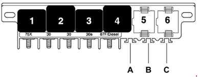
Mounting box in pressure box
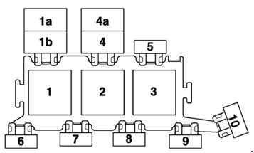
Appointment
| 1 | Secondary air pump relay – J299 (RS6) |
| 1a | Radiator fan relay (Allroad) – J26 |
| 1b | Coolant circulation relay after engine shutdown (Allroad) – J151 Auxiliary coolant pump relay – J496 |
| 2 | Secondary air pump relay – J299 |
| 3 | Motronic power relay – J271 (petrol engines) Diesel direct injection relay – J322 (diesel engines) Relay, anti-lock braking system – J64 (automatic transmission – 01J) |
| 4 | Coolant pump relay – J445 Coolant pump relay after engine shut down – J151 (RS6) |
| 4a | Not used |
| 5 | Engine control unit fuse – S102 Engine electronics fuse (Allroad) – S282 |
| 6 | Not used (left-hand drive vehicles) Glow plug fuse – S125 (V6 TDI, V8 TDI engines ) Glow plug fuse – S39 (4-cylinder engines) Radiator fan fuse – S94 (Allroad) |
| 7 | Glow plug fuse – S39 (engines: V6 TDI, V8 TDI) Secondary air pump fuse – S130 (petrol engines) Auxiliary heater fuse – S62 (right-hand drive vehicles) Not used (right-hand drive vehicles) |
| 8 | Auxiliary heater fuse – S62 (LHD) Not used (LHD) |
| 9 | Glow plug fuse – S125 (V6 TDI, V8 TDI engines ) Glow plug fuse – S39 (4-cylinder engines) Radiator fan fuse – S94 (Allroad) Coolant pump fuse – S78 (RS6) Not used (right-hand drive vehicles) |
| 10 | Fuel cooling pump fuse – S262 Fuse -1- (15) – S199 (automatic transmission 01J) Radiator fan control unit fuse – S142 (Allroad) Not used (right-hand drive vehicles) |
Individual fuses:
Left-hand drive vehicles:
– Auxiliary heater – S62 (from 2001)
Right-hand drive vehicles:
– Auxiliary heater – S62 (from 2001)
– Fuel cooling pump fuse – S262
– Fuse -1- (15) – S199 (automatic transmission 01J)
– Radiator fan control unit fuse – S142 (Allroad)