Volvo FH 4 represents the 3rd generation of serial heavy-duty vehicles of the Volvo company, which was produced in 2013, 2014, 2015, 2016, 2017, 2018, 2019, 2020, 2021, 2022, 2023 and 2024. During this time, the model was restyled. In our article, you will find a description of the fuses and relays of the Volvo FH 4 with block diagrams, photographs and their locations. We will highlight the fuse responsible for the cigarette lighter.

The purpose of fuses and relays may differ from that shown and depends on the year of manufacture, modification and level of electrical equipment of your car.
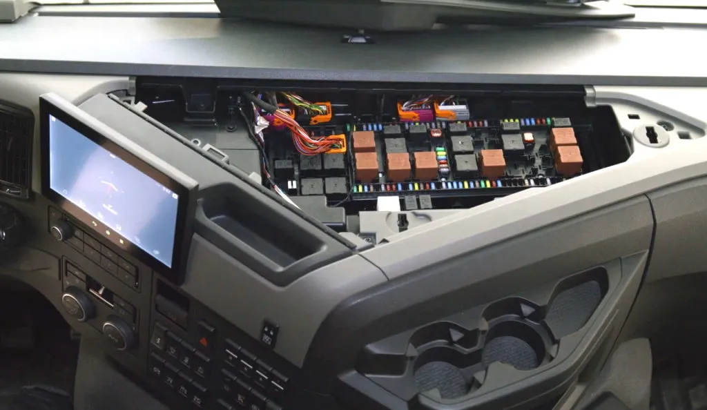
Fuse and relay box
The main fuse and relay box is located in the center console behind a protective cover.
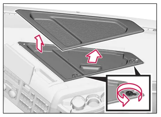
Check the information against your diagrams on the block cover.
| F 1 | 10A 12 Volt Power Socket |
| F 2 | – |
| F 3 | 10A TV preparation, power supply |
| F 4 | – |
| F 5 | – |
| F 6 | 5A Body Switch (Optional),Power Supply |
| F 7 | 30A Body Electrical Center (optional), Main Power Supply 1 (30A) |
| F 8 | 20A Body Electrical Center (optional), Main Power Supply 2 (20A) |
| F 9 | – |
| F10 | 3A USB |
| F11 | 15A Additional roof spotlights, EL1- |
| F12 | 15A Roof Flashing Beacon Signal Lamps, EL4 |
| F13 | 15A Driver and Passenger Seat Heater, Alcolock, Engine Power Supply |
| F14 | – |
| F15 | 10A Roof or Roof Light Stencil, EL 5 |
| F16 | 10A High beam inside stencil area, EL 0 |
| F17 | – |
| F18 | 3A HMIIOM(Human Machine Interface Input/Output Module) Power Supply |
| F19 | 15A BBM (Body Module (Optional)), Power Supply |
| F20 | 20A DDM/PDM (Driver/Passenger Door Module) Right Power Supply |
| F21 | 3A SID (Additional Instrument Panel) Power Supply |
| F22 | 5A Sun visor, bed tilt power supply |
| F23 | 3A Tachograph, power supply |
| F24 | 5A Devices, power supply |
| F25 | 3A Toll Collection System, Power Supply |
| F26 | – |
| F27 | 10A VMCU |
| F28 | 20A VMCU |
| F29 | 10A Right Mirror Heating |
| F30 | 10A Left Mirror Heating |
| F31 | 5A DACU (Driver Assistance Control Unit), |
| F32 | 10A APM (Air Pressure Monitoring) |
| F33 | 3A Wireless Remote Control |
| F34 | 5A Electric Front Lid Lock |
| F35 | 15A Parking Cooler Fan Control Unit |
| F36 | 5A Camera |
| F37 | 20A ABS/EBS, power supply |
| F38 | 20A CCM (Climate Control Module), |
| F39 | 20A Fuel Line Heater, |
| F40 | 3A Tachograph, ignition circuit power supply |
| F41 | 15A EMS (Engine Management System), ECU main power supply |
| F42 | 15A Controlled loads 1 EMS unit |
| F43 | 10A Fuel Filter Heater |
| F44 | 10A Controlled loads 2 EMS units |
| F45 | 30A Power supply for the cabin tilt pump motor |
| F46 | 20A ABS/EBS trailer, |
| F47 | – |
| F48 | – |
| F49 | 50A Main power supply for chassis body (optional) |
| F50 | 30A Auxiliary power supply for coffee maker |
| F51 | 20A Windshield Wiper Motor Low/High Speed On/Off |
| F52 | 15A Power supply for the sunroof motor |
| F53 | 5A Video Switch, |
| F54 | – |
| F55 | 3A Alarm, power supply. |
| F56 | 10A |
| F57 | 10A Interior Lighting |
| F58 | 15A Amplifier, Power Supply |
| F59 | 15A Converter, Top Shelf Power Supply |
| F60 | 15A Converter, Power Supply in the Dashboard |
| F61 | 20A DDM/PDM (Driver/Passenger Door Module) Left Power Supply |
| F62 | 5A OBD Diagnostic Connector, Power Supply |
| F63 | 10A CIOM (Cabin Input/Output Module) Power Supply |
| F64 | 15A 24V Power Socket 1 in Dashboard |
| F65 | 15A 24V power socket 2 in the sleeping area panel |
| F66 | 3A TIS (Transport Information System) and Telematics System, |
| F67 | 15A Cigarette Lighter |
| F68 | 15A VMCU |
| F69 | 15A Cabin Parking Heater, Power Supply |
| F70 | 20A TECU (Transmission Electronic Control Module) |
| F71 | 15A Headlight washer pump motor |
| F72 | 5A |
| F73 | 30A Body Electrical Equipment Center (optional), ignition power supply |
| F74 | 20A Body Electrical Center (optional), ignition power supply |
| F75 | 10A Refrigerator, |
| F76 | 15A |
| F77 | – |
| F78 | – |
| F79 | – |
| F80 | 3A LECM (Living Environment Management Module), |
| F81 | 5A SRS (Supplemental Restraint System), Airbag, Ignition Circuit Power Supply |
| F82 | 3A GLONASS |
| F83 | – |
| F84 | – |
| F85 | 3A FMS (Fleet Management System) Connector Ignition Power Supply |
| F86 | – |
| F87 | – |
| F88 | 5A Alcolock, power supply |
| F89 | – |
| F90 | 15A Seat Motor |
| F91 | 10A FMS connector, power supply |
| F92 | Tachograph, adaptation-switch ADR |
| F93 | Microwave oven |
| F94 | Adaptation-switch ADR |
| F95 | Adaptation-switch ADR |
Relay
- K01 -.
- K02 Relay, refrigerator
- K03 Relay, sunroof motor 2
- K04 Relay, sunroof motor 1
- K05 Relay, front wiper on/off
- K06 Relay, Front Wiper, Low/High Speed
- K07 Relay, body electrical centre (optional), power supply
- K08 Relay, additional equipment
- K09 Relay, seat heater
- K10 Relay, body electrical system centre (optional), additional spotlights
- K11 Relay, power supply 4
- K12 Relay, stencil with illumination on the roof
- K13 Relay, flashing beacon signal lamps
- K14 Relay, power supply 3
- K15 Relay, high beam inside stencil area
- K16 Relay, headlight washer pump
- K17 TECU (Electronic Transmission Control Module)
- K18 -.
- K19 -.
- K20 Relay, Ignition Circuit BB
- K21 Relay, heated mirrors
- K22 Relay, ignition
- K23 -.
- K24 Relay, adjustable seat
- K25 -.
- K26 -.
- K27 Relay, Engine Management System
- K28 Relay, Cabin Tilt Pump
- K30 Relay, rear lift/crane activation
- K31 Relay, additional front spot lamp EL6
- K32 Relay, side working reversing light EL2
- K33 Relay, working headlight, cab/body EL3
- K34 -.
- K35 -.
- K48 Power relay, engine preheating
- K52A Power relay, FLL motor 1-
- K52B Power Relay, FLL Motor 2-
- K65 Relay, starter-
- K69 Relay, fuel heater
- K70A Relay, adaptation – switch ADR3/SLP
- K70B Relay, adaptation – switch ADR3/SLP
- K71 Relay, audio switch, telematics, L+
- K90
- K91
- K92
- K95 Relay, Microwave
- K96
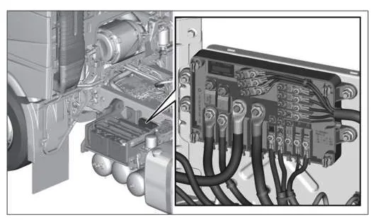
Block near the battery
The high power fuse box is located next to the battery.
- 200A Body
- 100A FRC Driver’s Cabin Fuse & Relay Center
- 30A Front Chassis Control FCIOM
- 30A Chassis Control Center CCIOM
- 30A Rear Chassis Control RCIOM
- 30A Front Chassis Control FCIOM
- 30A Chassis Control Center CCIOM
- 30A Rear Chassis Control RCIOM
- 30A Front Axle Control FAS
- 40A Parking Cooler PCCU
- 23A ACM Aftertreatment Control Unit
- 23A Auxiliary Axle Control