In the following post we provide diagrams and locations of fuse and relay boxes for the New Holland TL70, TL80, TL90, TL100.
The New Holland TL70, TL80, TL90 and TL100 are a series of agricultural tractors produced by New Holland from 1998 to 2003. They were designed for small and medium-sized farms and also as machines for municipal work. This series replaced the previous 7740 series.
The TL series tractors are equipped with engines ranging from 70 to 100 hp that meet Tier 1 emission standards. They run on diesel fuel and feature a mechanical transmission with 16 forward and 16 reverse gears. They also have a distribution box that allows easy switching between field and road modes.
These tractors are equipped with a self-locking front axle for excellent traction on all types of ground. All models have a hydraulic control system that allows easy raising and lowering of agricultural implements.
The TL series also features a number of operator amenities, such as ergonomic seats, ventilated cabs, as well as air conditioning and heating systems. The tractors are also equipped with automatic speed control systems for more precise work and increased productivity.
All in all, the TL series are robust and powerful tractors that are perfect for agricultural and municipal work. Their comfortable cabs, operator amenities and precise control systems make working with them easier and more efficient.
Checking and replacing fuses
As you know, fuses protect against overloading the electrical system of our cars. When a component stops working, it is most likely that a circuit breaker has tripped or a fuse has blown. Therefore, the fuse responsible for the component should be checked before repair. A blown fuse will be indicated by a melted or completely ruptured tape inside the fuse.
Remember this before replacing the fuse!
- remove the ignition key
- check that everything has been switched off
- always replace fuses with the same amperage.
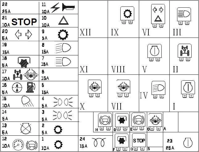
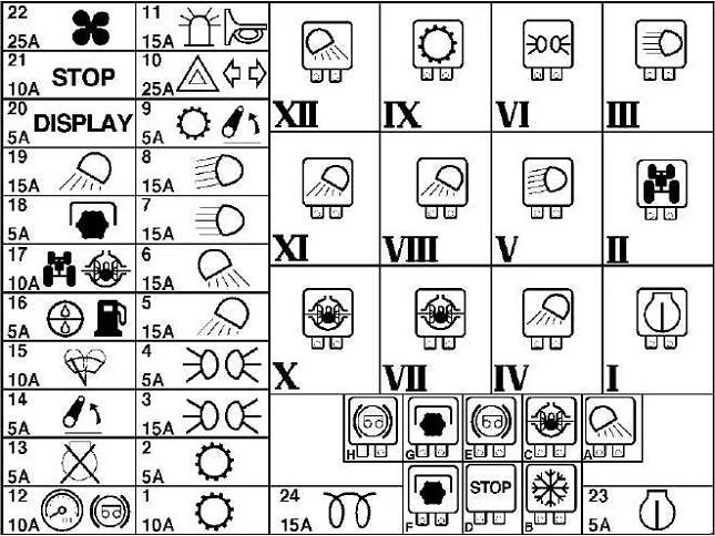
| Number | Amps [A] | Description |
| 1 | 10 | With Power Shuttle: Power Shuttle circuit, (+ key) |
| 2 | 5 | Without Power Shuttle: 2-speed Power Shift circuit With Power Shuttle: Power Shuttle circuit, (+ key) |
| 3 | 5 | Front right and rear left position lights |
| 4 | 5 | Front left and rear left side lights, controls and instrument lighting |
| 5 | 15 | Without cab: Front work lights in grille With cab: Lower front work lights |
| 6 | 15 | With cab: rear work lights |
| 7 | 15 | High beam |
| 8 | 15 | Low beam headlights |
| 9 | 5 | Without cabin with Power Shuttle: Power Shuttle circuit, (+ battery) With cabin: electronic lifting circuit With cabin with Power Shuttle: electronic lifting circuit and Power Shuttle, (+ battery) |
| 10 | 15 | Without cabin: hazard warning lights |
| 25 | With cabin: indicators and hazard warning lights | |
| 11 | 15 | Horn, power socket, buzzer (with Power Shuttle), cigarette lighter (with cab), rotating beacon (with cab), overhead lighting (with cab with Power Shuttle), radio (with cab with Power Shuttle) . |
| 12 | 10 | + Instruments, Seat Safety Circuit, Trailer Brake |
| 13 | 5 | Engine shutdown solenoids |
| 14 | 5 | With cabin: electronic lifting circuit, (+ key) |
| 15 | 10 | Without cab: Rear work light With cab: Rear and front window wipers, front and rear window wiper pump |
| 16 | 5 | Sediment filter circuit, air conditioning compressor circuit (with cabin) |
| 17 | 10 | 4WD circuit, differential lock, brake light (with cabin) |
| 18 | 5 | Rear power take-off circuit |
| 19 | 15 | With cab: Front overhead work lights |
| 20 | 10 | Without cabin: indicators |
| 5 | With cabin: digital instrument circuit | |
| 21 | 10 | Brake lights, seat (with cabin) |
| 22 | 25 | With cabin: fan, radio |
| 23 | 5 | Starter safety circuit |
| 24 | 15 | Thermostart |
| Relay | ||
| I | 70A Engine Start Relay | |
| II | Electrohydraulic 4 wheel drive. relay circuit | |
| III | Full beam headlamp relay | |
| IV | reserve | |
| V | Low beam relay | |
| VI | With cab: Side/tail light circuit relay Without cab: Electronic flasher | |
| VII | Differential lock and brake light relay | |
| VIII | With cab: Front/top work light relay | |
| IX | 2-speed Power Shift circuit relay | |
| X | Differential lock circuit relay | |
| XI | With cab: Front/lower work light circuit relay | |
| XII | With cab: Rear work light circuit relay | |
| A | — | |
| B | With cabin: conditioner circuit relay | |
| C | Differential lock circuit relay | |
| D | Brake Light Circuit Relay | |
| E | Trailer Brake Circuit Relay | |
| F | Electrohydraulic PTO circuit relay | |
| G | Electrohydraulic PTO circuit relay | |
| H | Trailer Brake Circuit Relay | |
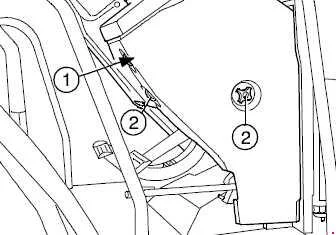
| Number | Amps [A] | Description |
| 1 | 40 | 40A power socket. |
| 2 | 40 | Fuses 3, 4, 7, 8, 9, 10, 11 |
| 3 | 50 | Fuses 1, 2, 12, 13, 14, 15, 16, 17, 18, 20, 21, 22, 23, 24 and starter circuit |
| 4 | 50 | With cab: Fuses 5, 6, 19, 25, 26 (work lights) |