Dacia Duster — belongs to the class of crossovers. It was first introduced to the European market back in 2009, 2010, 2011, 2012, 2013, 2014, 2015, 2016, 2017, 2018, 2019, 2020, 2021,2022, 2023, 2024 and to the present. During this period, the car was restyled. We present a description of the fuse boxes and relays for Renault Duster with two main versions (pre- and restyled versions). We will show the block diagrams, the purpose of their elements, and note the fuse responsible for the cigarette lighter.
Please note that the number of fuses and relays, as well as the block diagrams themselves, may differ from this material and depend on the electrical equipment, year of manufacture and country of delivery of the vehicle.
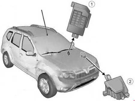
Location of fuse and relay boxes in Dacia Duster:
- On the left side at the end of the instrument panel.
- In the engine compartment, immediately behind the battery.
Description for pre-restyling
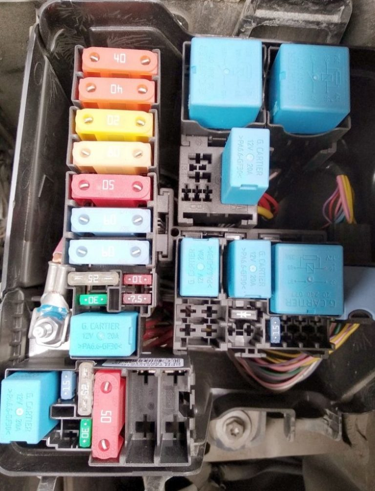
Block under the hood
General photo – diagram
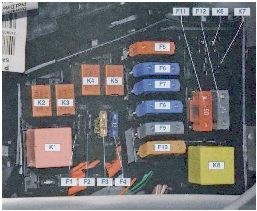
Description of fuses
| F1 | Not used |
| F2 | Not used |
| F3 (25) | Chains: fuel pump and ignition coils; main relay K5 of the engine management system |
| F4 (15) | Air conditioning compressor electromagnetic clutch circuit |
| F5 (40) | Power circuits: low speed cooling fan relay short circuit |
| F6 (60) | Circuits protected by fuses F9, F10, F28, F29, F30, F31, F32, F36 of fuse block 1 in the passenger compartment |
| F7 (60) | Circuits protected by fuses F13, F14, F15, F16, F17, F18, F19, F20, F24, F26, F27, F37, F38, F39 of the fuse box in the passenger compartment |
| F8 (60) | Circuits protected by fuses F1, F2, F3, F4, F5, F11, F12 of the fuse box in the passenger compartment |
| F9 (25) | Circuits under voltage in positions S and A of the ignition key |
| F10 (80) | Power circuits of the relay for switching on the electric heater of the passenger compartment |
| F11 (50) and F12 (25) | ABS control unit circuits |
Relay designation
- K1 – High speed cooling fan relay
- K2 – Air conditioner relay
- KZ – Low speed relay of the cooling system fan
- K4 – Fuel pump and ignition coil relay
- K5 – Main relay of the engine management system
- K6 – Not used
- K7 — Fog lamp relay. If it is not present, then the fog lamps are not installed.
- K8 — Heater fan relay
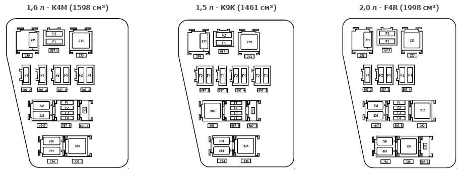
Other versions of this block.
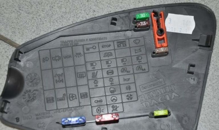
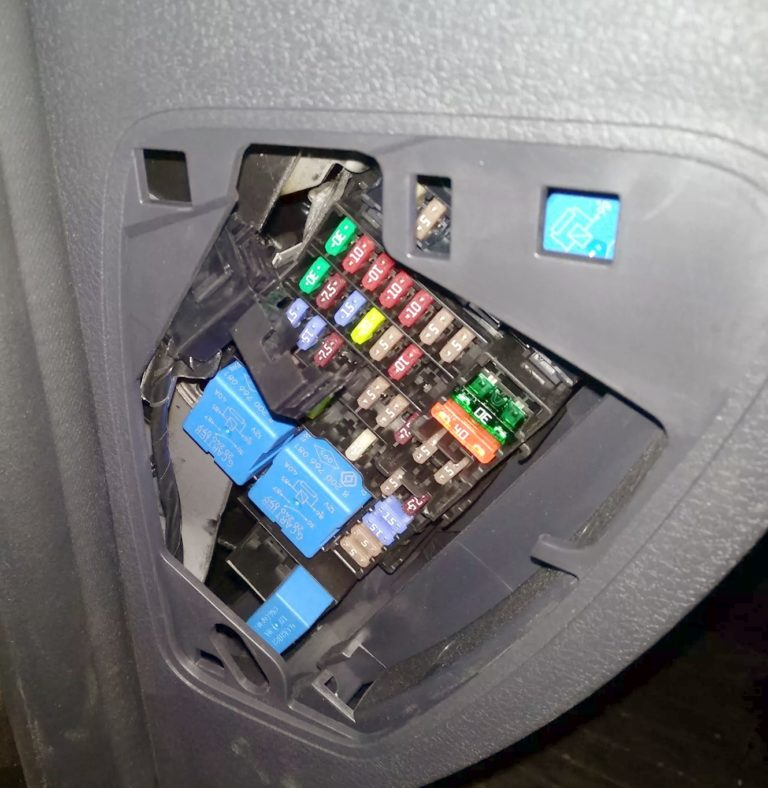
Block in the cabin
Located at the end of the instrument panel on the driver’s side behind the cover.
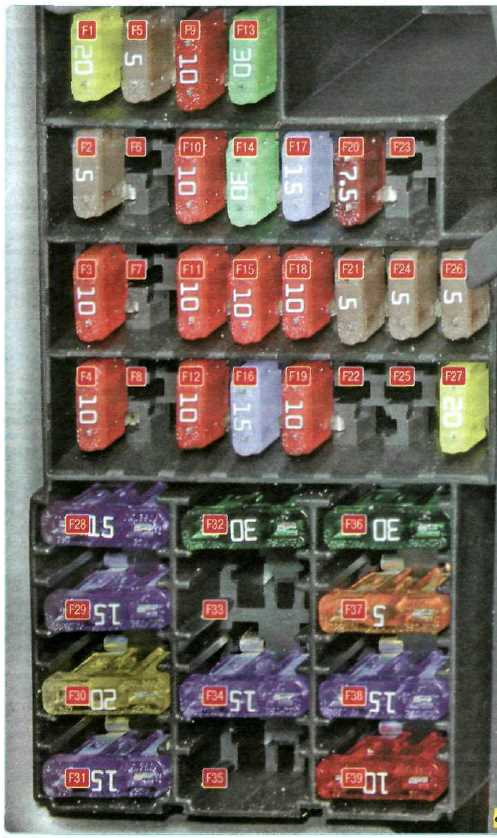
| F1 (20) | Chains: windshield wiper; windings of the tailgate glass heating relay |
| F2 (5) | Chains: power supply for the instrument cluster; windings of relay K4 of the fuel pump and ignition coils; power supply for the engine management system ECU from the ignition switch; |
| F3 (10) | Brake light circuits |
| F4 (10) | Circuits: direction indicator lamps; engine management system diagnostic connector (pin 1); immobilizer coil; switching unit |
| F5 (5) | Rear axle electromagnetic clutch control circuit |
| F6 | Reserve |
| F7 | Reserve |
| F8 | Reserve |
| F9 (10) | Left Headlight Low Beam Lamp Circuit |
| F10 (10) | Right headlight low beam lamp circuit |
| F11 (10) | Chains: left headlight high beam lamps; high beam indicator in the instrument cluster |
| F12 (10) | Right headlight high beam lamp circuit |
| F13 (30) | Rear door electric window lifter circuits |
| F14 (30) | Front door electric window lifter circuits |
| F15 (10) | ABS control unit circuit |
| F16 (15) | Driver and front passenger seat heating circuits |
| F17 (15) | Sound signal chains |
| F18 (10) | Chains: Left headlight side light bulbs; Left rear light side light bulbs |
| F19 (10) | Chains: Right headlamp side light bulbs; Right rear light side light bulbs; Number plate light bulbs; Glove compartment light bulbs; Instrument cluster and control illumination on the instrument panel, console and floor tunnel trim |
| F20 (7.5) | Rear fog lamp circuit |
| F21 (5) | External rear view mirror heating element circuits |
| F22 | Reserve |
| F23 | Reserve |
| F24 (5) | Power steering control circuit |
| F26 (5) | Airbag control unit circuit |
| F27 (20) | Chains: parking sensors; reversing lights; windshield and tailgate glass washers |
| F28 (15) | Chains: interior light lamps; trunk light lamps; head unit illumination lamps |
| F29 (15) | Circuits: intermittent windscreen wiper; direction indicator switch; hazard warning switch; central locking control; buzzer; engine management system diagnostic socket |
| F30 (20) | Central lock chains |
| F31 (15) | Fog light chain |
| F32 (30) | Power circuit of the heated glass relay of the tailgate |
| F33 | Reserve |
| F34 (15) | Rear axle electromagnetic clutch circuit |
| F35 | Reserve |
| F36 (30) | Power circuit of relay K8 heater fan |
| F37 (5) | External rear view mirror electric drive chains |
| F38 (15) | Cigarette lighter renault duster; power supply of the head unit of sound reproduction from the ignition switch |
| F39 (10) | HVAC Motor Relay |
Fuse number 38 is responsible for the cigarette lighter.
Separately, under the anti-theft device, along the dashboard beam, there may be an additional interior heater relay (1067 – 1068), and under the instrument panel, a rear window heating relay (235).
Designation for restyled
Block under the hood
Photo
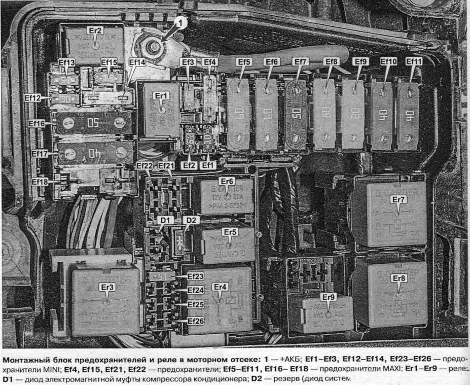
Purpose of fuses
| Ef1 | 10A Fog lights |
| Ef2 | 7.5A Electrical Equipment Control Unit |
| Ef3 | 30A Rear window defroster, exterior mirror defrosters |
| Ef4 | 25A Electronic Stability Control Unit |
| Ef5 | 60A Fuse circuits P11, P24-P27, P34, P39, P41 |
| Ef6 | 60A Ignition switch, fuse circuits P28. P31, P38, P43, P46, P47 |
| Ef7 | 50A Electronic Stability Control Unit |
| Ef8 | 80A Socket in the Luggage Compartment |
| Ef9 | 20A Reserve |
| Ef10 | 40A Heated windshield 1 |
| Ef11 | 40A Heated windshield 2 |
| Ef12 | 30A Starter |
| Ef13 | 15A Reserve |
| Ef14 | 25A Electronic Engine Management System |
| Ef15 | 15A A/C Compressor Clutch Relay, A/C Compressor Clutch |
| Ef16 | 50A Electric cooling fan |
| Ef17 | 40A Automatic transmission control unit |
| Ef18 | 80A Electric Power Steering Pump |
| Ef19 | Reserve |
| Ef20 | Reserve |
| Ef21 | 15A Oxygen sensors, Evaporative canister purge valve, Camshaft position sensor, Variable valve timing |
| Ef22 | Electronic engine control unit (ECU), control unit of the electric cooling fan, ignition coils, fuel injectors, fuel pump |
| Ef23 | Fuel pump |
Purpose of the relay
- 20A Er1 – Horn Relay
- 20A Er2 – Alarm buzzer relay
- 35A Er3 – Starter Relay 1
- 35A Er4 – Engine Management System Main Relay
- 20A Er5 – Air Conditioning Compressor Clutch Relay
- 20A Er6 – Fuel pump relay
- 35A Er7 — Windscreen heating relay 2 / Cooling system electric fan relay
- 35A Er8 – Windscreen heating relay 1
- 20A Er9 – Starter Relay 2
Block in the cabin
Photo of the block
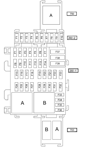
Pinout of fuses on 260-2
- Reserve
- 25A — Electrical equipment control unit, left headlight, right headlight
- 5A – All-wheel drive transmission (4WD)
- Reserve / 15A Additional control unit electrical equipment
- 15A Rear auxiliary equipment socket ( socket )
- 5A — Electrical equipment control unit
- Reserve
- 7.5A – No data
- Reserve
- Reserve
- Relay A – Rear window lifter lock
Pinout for 260-1 (main board)
- 30A – Electric window lifter front door
- 10A – Left headlight high beam
- 10A – Right headlight high beam
- 10A – Low beam left headlight
- 10A – Right low beam headlight
- 5A – Rear lights
- 5A – Front side lights
- 30A – Electric rear window
- 7.5A – Rear fog light
- 15A – Sound signal
- 20A – Automatic door lock
- 5A – ABS – ESC systems, brake light switch
- 10A – Ceiling light, luggage compartment light, glove compartment light
- Not used
- 15A – Windscreen wiper
- 15A – Multimedia system
- 7.5A – Fluorescent lamps
- 7.5A – Stop light
- 5A – Injection system, instrument cluster, central electronic switching unit in the passenger compartment
- 5A – Airbag
- 7.5A – All-wheel drive transmission with 4 driving wheels (4WD), reverse gear
- 5A – Power steering
- 5A — Speed controller/limiter, rear window relay, seat belt warning light, parking distance control system, auxiliary interior heating relay
- 15A — CECBS (central electronic switching unit of the passenger compartment)
- 5A — CECBS (central electronic switching unit of the passenger compartment)
- 15A – Direction indicators
- 20A – Steering column switches
- 15A – Sound signal
- 25A – Steering column switches
- Not used
- 5A – Instrument panel
- 7.5A — Radio, air conditioning control panel, interior ventilation, rear socket for electrical accessories
- 20A – Cigarette lighter
- 15A – Diagnostic connector and connector for audio system
- 5A – Heated rear view mirror
- 5A – Electrically adjustable exterior rearview mirrors
- 30A — Central electronic switching unit of the passenger compartment, starter
- 30A – Windscreen wiper
- 40A – Car interior ventilation
- Relay A – Electric fan of the air conditioning system
- Relay B – Mirror heating
Fuse number 33 is responsible for the cigarette lighter.
Relay 703: B – Reserve, A – Additional socket in the luggage compartment.