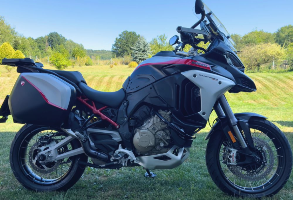
Ducati Multistrada – Fuses, Relays and Electrical Wiring Diagram
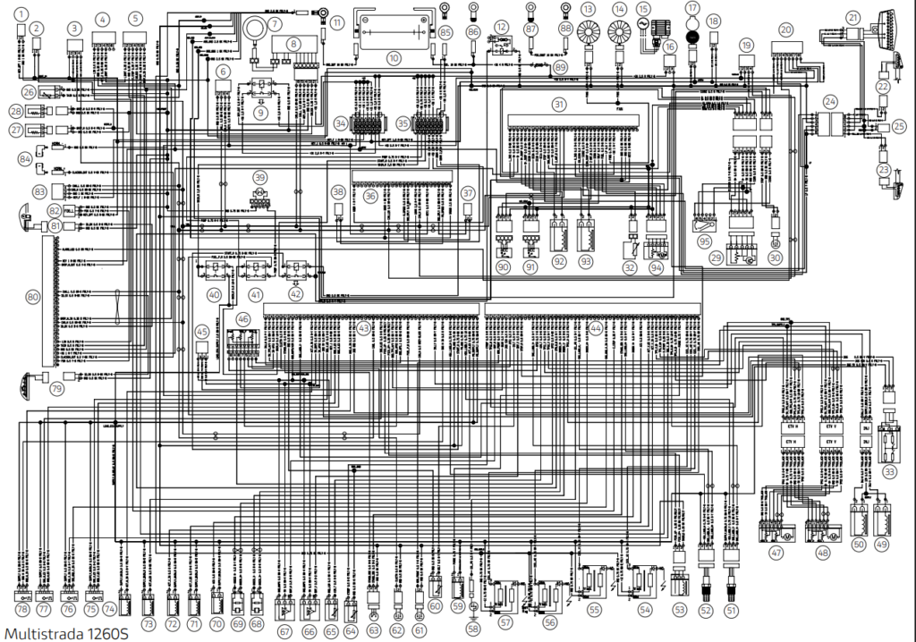
Electrical wiring Ducati Multistrada
It includes the following main components:
Headlight Ducati Multistrada
LED low beam headlights: 2 Ostar LE UW U1A4 01 LEDs.
LED high beam headlights: 8 Oslon GW CSSRM1 LEDs. PC. LED turning headlights: 2 Oslon GW CSSRM1 LEDs. PC.
LED Parking Lights: 2 LEDs STW8Q14C.
Turn signals Ducati Multistrada
LED Front Indicators (Europe/US): 12 x Dominant Primax NAZY-BGH-MN3-1 LEDs.
Rear LED Indicators (Europe): 1 PC AMBER PHILIPS LXM2-PL01 LED.
Rear Lamp Indicators (US): 1 x RY10W 12V/10W lamp in amber yellow.
Taillight Ducati Multistrada
LED parking lights: 2 OSRAM LEDs LA-W5SM-JYKY-24-1.
LED brake lights: 10 OSRAM LEDs LA-E6SF-BBCB-24-1.
LED license plate lighting: 3 CREE CLA1A-WKW-CXAYB453 LEDs.
Fog lights Ducati Multistrada
LED fog lights (Enduro personalization): 1 Altilon LAFL-C4S-0850 LED.
Horn.
Brake light switches. Battery 12 V / 10 Ah
DENSO alternator 12 V / 500 W. Electronic regulator protected by a 30 A fuse.
DENSO starter, 12 V / 0.7 kW.
Fuses Ducati Multistrada
1 2 3 4 5 6 7
A
Fig. 334
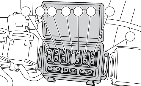
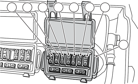
Twelve fuses protect the electrical components. All fuses, except for the one located on the electric ignition contactor, are located inside the front and rear fuse boxes. Each box contains one spare fuse:
– Box (A): 7.5 A; 15 A; 25 A.
– Box (B): 10 A; 15 A; 25 A.
See the fuse usage and current rating in the relevant table.
1 2 3 4 5 6 7
B
Fig. 335
The front fuse box (A) is located under the driver’s seat.
Access to the fuses used is possible after the protective cover is opened, on the surface of which the installation procedure and rated current are indicated.
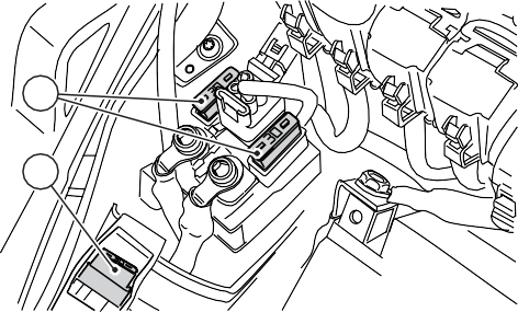
The rear fuse box (B, and ABS fuses (C, Fig. 336) are located under the driver’s seat.
remove the driver’s saddle, see page 323. Access to the fuses is possible after the protective cover is removed, on the surface of which the installation procedure and rated current are indicated.
Front fuse box designations (A)
Gender.
Consumers
Meaning.
1
KEY EMS / ABS / IMU
5 A
2
KEY DSB / BBS
15 A
3
KEY Headlights
15 A
4
–
–
5
KEY Accessories
10 A
6
+30 Hands Free
25 A
7
+30 Diagnostics / Recharging
7,5 A
Designations of the rear fuse box (B)
Gender.
Consumers
Meaning.
1
+30 EMS relays
25 A
2
+30 Fuel Pump Relay
10 A
3
+30 starter relay
7,5 A
Designations of the rear fuse box (B)
4
+30 Instrument panel
10 A
5
+30 Black Box System (BBS)
10 A
6
+30 ABS UBMR
25 A
7
+30 ABS UBMR
15 A
The 30 A starter main fuse (C) is located under the rider’s seat on the right side. Remove the protective cover to access it.
D
C
Redundant fuses at 30 A (D) are located on the ignition contactor; Remove the protective cover to access them. A blown fuse can be identified by a broken thread of the internal conductor (F).
Important information
To avoid a short circuit, the fuses must be replaced after the ignition key has been turned to the OFF position.
Attention
Never use fuses with different characteristics than those prescribed. Failure to comply with this rule can lead to damage to electrical wiring and even fires.
Designations on the wiring/injection system diagram
Front socket, 12 V
Navigator
Bluetooth
Left Switch
Right Switch
Inertial Sensor
Anti-theft device
Hands free
Hands Free Relay
Battery
Grounding electrical wiring
Contactor
Left impeller
Right impeller
Alternator
Regulator
USB connector
Rear socket, 12 V
Data Acquisition System / Diagnostics
Anti-theft alarm
Taillight
Right rear turn signal
Left rear turn signal
Rear wiring
License Plate Illumination Lamp
Temperature sensor
Left heated handle connector (optional)
Right heated handle connector (optional)
Outlet valve actuator
Rear brake light
Motorcycle Control Unit (BBS)
Gasoline level
Ducati Quick Shift (DQS)
Fuse box (2)
Fuse box (1)
ABS Unit
Rear speed sensor
Front speed sensor
Fuel pump
Main Unit Relay
Fuel Pump Relay
Starter Relay
Injection Unit A Connector (EMS)
Injection Unit Connector B (EMS)
Transmission Sensor
Throttle Stick Position Sensor (APS)
(ETV) Vertical
(ETV) Horizontal
Main Vertical Injector
Main Horizontal Injector
Vertical Oxygen Sensor
Horizontal Oxygen Sensor
RPM/Sync sensor
Vertical Cylinder Secondary Coil
Vertical Cylinder Main Coil
Secondary Coil of Horizontal Cylinder
Horizontal Cylinder Main Coil
Oil Pressure Sensor
Purge valve
Oil temperature
Brake lamp switch
Clutch Switch
Side Stand Switch
Engine temperature sensor
Air temperature sensor
Vertical MAP Sensor
Horizontal MAP Sensor
Vertical knock sensor
Horizontal knock sensor
Secondary sensor. Air
EX Vertical Sync Sensor
Vertical IN Timing Sensor
Horizontal EX Sync Sensor
Horizontal IN Timing Sensor
Vertical EX Sync Connector
Vertical IN Sync Connector
Horizontal EX Sync Connector
Horizontal IN Sync Connector
Left front turn signal
Dashboard
Right front turn signal
Fog lights (optional)
Front headlights
Horn
He will. ABS
He will. starter relay
He will. Starter
Starter
Starter fuse
Front acceleration sensor (on the wheel)
Front acceleration sensor (frame-mounted)
Front fork drive
Rear shock absorber drive
Rear shock absorber spring preload mechanism
Pendulum position sensor
Wire color coding
B Blue W White
V Purple Bk Black
Y Yellow
R Red
Lb Blue
Gr Grey
G Green
Bn Brown
O Orange
P Pink
Electrical wiring Ducati Multistrada
Ducati Multistrada – Fuses, Relays and Electrical Wiring Diagram