The Volkswagen ID.4 was produced in 2020, 2021, 2022, 2023, 2024, 2025 on a common base with the Volkswagen ID.5 with the E21 and E39 body designations. During this time, the model has undergone a facelift. In this article, you will find a description of the fuses and relays of the Volkswagen ID 4 ID 5 with diagrams of the fuse blocks and their location. Let’s highlight the fuse responsible for the cigarette lighter.
Engine compartment
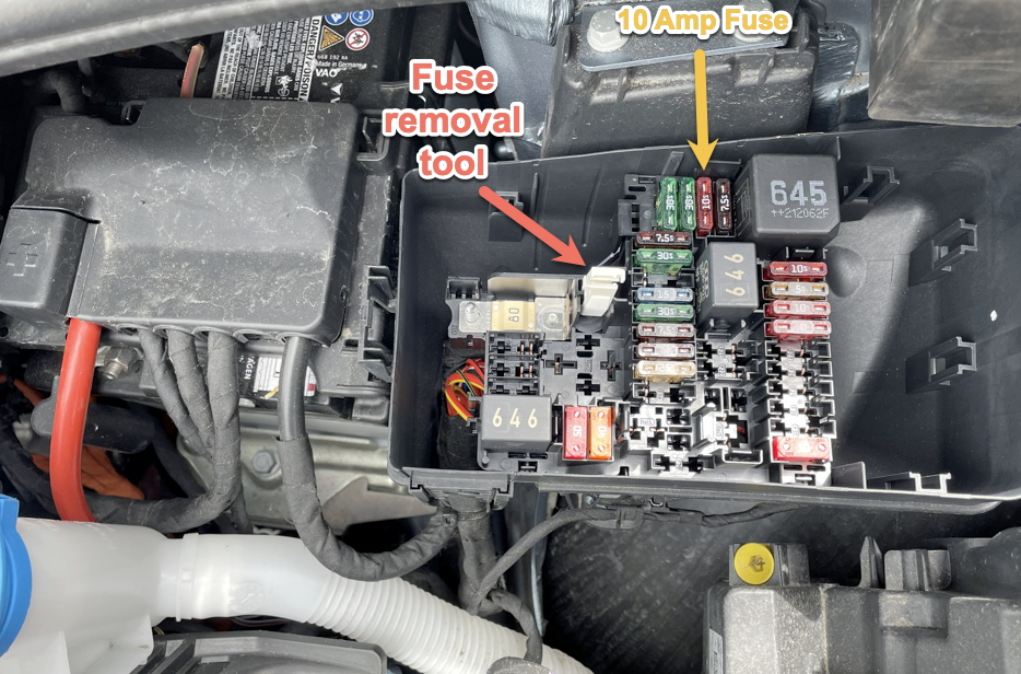
Under the hood on the left side, in the engine compartment, there are 2 fuse blocks.
Fuse and relay block
Arrangement
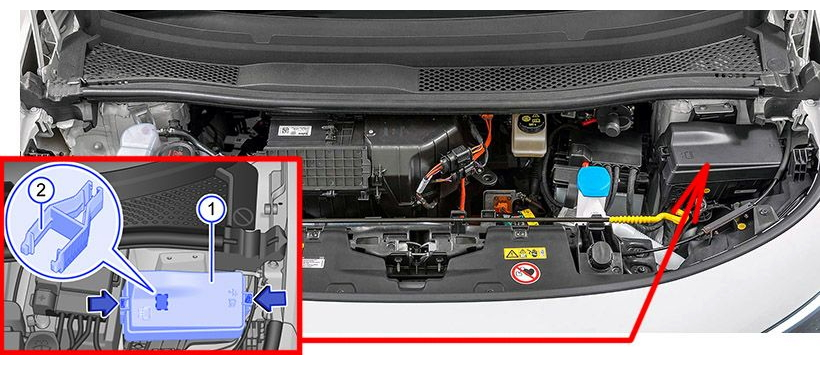
Photo example
Scheme
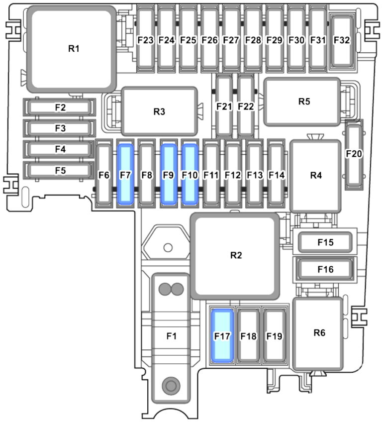
Appointment
| F1 | – |
| F2 | ABS control unit 7.5A |
| F3 | 10A High Voltage Battery Charger |
| Power and control electronics of the electric drive | |
| Power and control electronics 2 for electric drive | |
| F4 | 30A Front left headlight |
| F5 | 30A Front right headlight |
| F6 | Adaptive cruise control 7.5A |
| F7 | 30A Front right wipers |
| F8 | – |
| F9 | 15A On-board network control unit (signal) |
| F10 | Wiper motor control unit 30A |
| Front wipers, left | |
| F11 | 7.5A Air conditioner relay |
| F12 | Engine sound generator module 7.5 A 1 |
| F13 | ABS control unit 25A |
| F14 | – |
| F15 | ABS control unit 40A |
| F16 | Radiator fan 50A |
| F17 | 40A Heated windshield |
| F18 | – |
| F19 | – |
| F20 | – |
| F21 | – |
| F22 | – |
| F23 | 10A Engine/motor control unit |
| F24 | Radiator fan 5A |
| F25 | 10A coolant pump for high voltage battery |
| PTC heating element 3 | |
| F26 | 10A Coolant pump for low temperature circuit |
| Radiator roller shutter control motor | |
| F27 | – |
| F28 | – |
| F29 | – |
| F30 | – |
| F31 | – |
| F32 | Brake booster 50A |
| R1 | Main relay |
| R2 | Windshield heating relay |
| R3 | Horn relay |
| R4 | – |
| R5 | – |
| R6 | Air conditioner relay |
Power fuse box
This unit is installed on the battery compartment cover, next to the fuse and relay block.
Scheme
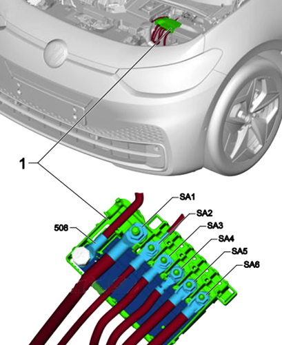
Marking
| 508 | Battery |
| SA1 | Voltage converter 350A |
| SA2 | Battery Monitor Control Unit 80A |
| Power steering control unit | |
| SA3 | Fuse holder 100A C (under the panel) |
| SA4 | Fuse holder 100A C |
| SA5 | – |
| SA6 | 125A Fuse holder B (under-hood fuse box) |
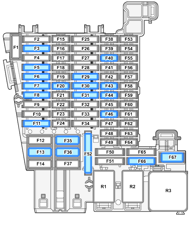
Passenger lounge
Fuse and relay block
In the cabin, the fuse and relay block is located on the left under the instrument panel.
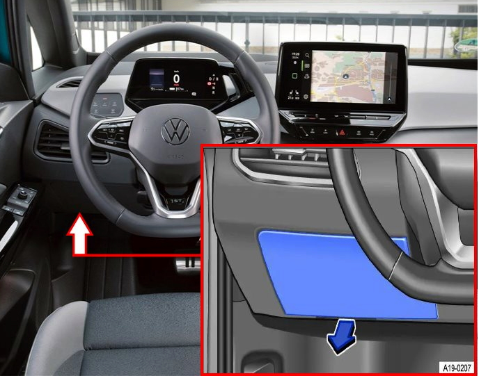
Example for right-hand drive vehicles.
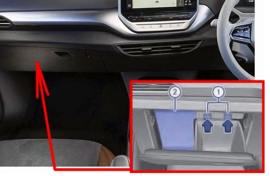
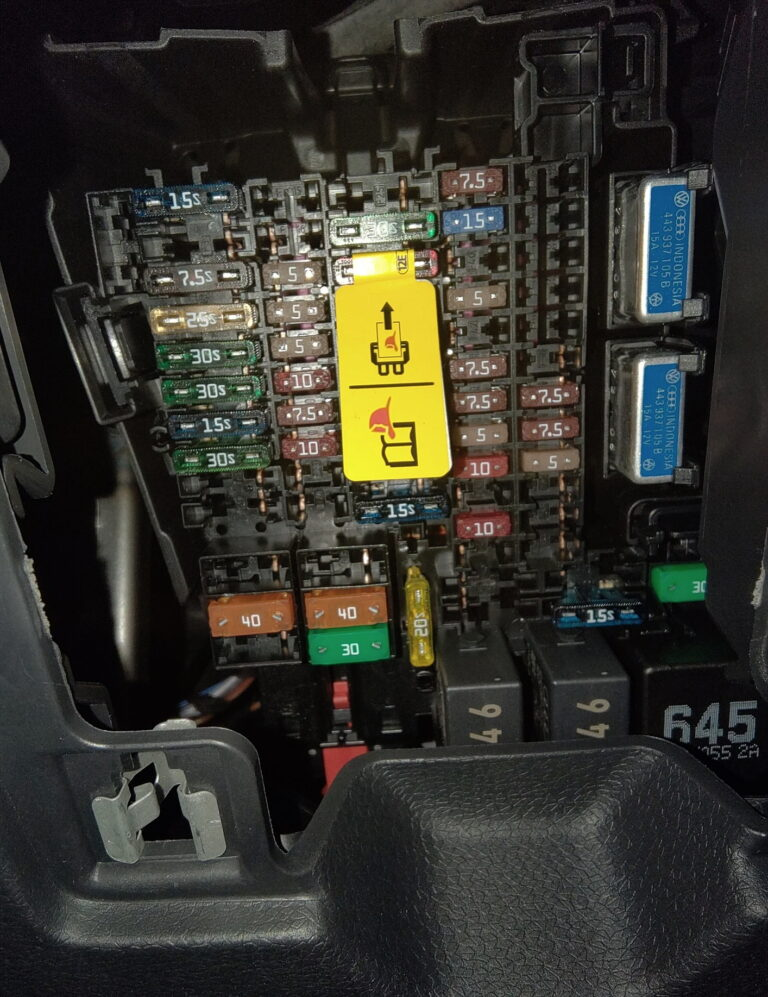
Photo example
Scheme
Localization
| SC1 | – |
| SC2 | 15A Airbag control unit |
| SC3 | 25A Trailer detector control unit |
| SC4 | 7.5A Front camera for driver assistance systems |
| SC5 | 25A On-board network control unit (left exterior lighting) |
| SC6 | 30A On-board network control unit (interior lighting) |
| SC7 | 30A Heater and air conditioning control unit (heated seats) |
| SC8 | 15A Sliding sunroof control unit |
| SC9 | Driver’s door control unit 30A (for left-hand drive models) |
| Front passenger door control unit (For right-hand drive models) | |
| Driver’s rear door control unit (for left-hand drive models) | |
| Rear passenger door control unit (For right-hand drive models) | |
| SC10 | 10A Tail light |
| Rear center light unit | |
| SC11 | 15A Trailer detector control unit |
| SC12 | – |
| SC13 | 40A On-board network control unit (central locking) |
| SC14 | 30A Digital audio control unit |
| SC15 | – |
| SC16 | – |
| SC17 | 5A Parking assistance control unit |
| Lane change assistant control unit | |
| Lane change assist control unit 2 | |
| SC18 | 5A Electronic steering column lock control unit |
| Electric trunk lid opening control unit | |
| Interface for logging in and starting the system | |
| Control unit 2 anti-burglary protection | |
| Control unit 3 anti-burglary protection | |
| Control unit 4 anti-burglary protection | |
| Control unit 5 anti-burglary protection | |
| Mobile login and launch authorization system control unit | |
| Engine Sound Generator Module 2 | |
| SC19 | 5A Emergency call module control unit and communication unit |
| Control unit with driver information system display | |
| SC20 | 7.5/10A Telephone bracket |
| Transmission and reception stabilization control unit | |
| USB connection 1 | |
| SC21 | 7.5A Rear cover handle |
| Top view camera control unit | |
| SC22 | 10A Engine/motor control unit |
| SC23 | 5A Internet access control unit |
| SC24 | 10A Right rear light group |
| Rear center light unit | |
| SC25 | 25A Front left seat belt |
| SC26 | Driver’s door control unit 30A (for right-hand drive models) |
| Front passenger door control unit (for left-hand drive models) | |
| Driver’s rear door control unit (for right-hand drive models) | |
| Rear passenger door control module (left-hand drive models) | |
| SC27 | 25A Front right seat belt |
| SC28 | 10A battery regulation unit |
| High voltage system service connector | |
| SC29 | 15A Trailer detector control unit |
| SC30 | 20/25A Information electronics control unit 1 |
| SC31 | 25A Trailer detector control unit |
| SC32 | 25A On-board network control unit (right exterior lighting) |
| SC33 | – |
| SC34 | 15A Heating and air conditioning control unit |
| SC35 | 40A Heated rear seats |
| SC36 | 40A Supply air fan control unit |
| SC37 | Rear cover control unit 30A |
| SC38 | 7.5A Front left massage seat control unit |
| Front right massage seat control unit | |
| SC39 | 15A Steering column electronics control unit |
| SC40 | 7.5/10A horn |
| SC41 | 5A diagnostic data bus interface |
| SC42 | – |
| SC43 | 7.5 A Control and display unit for rear air conditioning system |
| Carbon dioxide concentration sensor in the cabin | |
| Car interior temperature sensor | |
| Rear window heating relay | |
| SC44 | 7.5 A power window control unit in the driver’s door |
| Diagnostic connection | |
| Light switch (low beam) | |
| rain and light sensor, | |
| Background lighting | |
| ID. light | |
| SC45 | 5A Steering column electronics control unit |
| SC46 | 7.5/10A Front information display unit and control unit control unit |
| Head-up display control unit | |
| SC47 | Electronic shock absorber control unit 10A |
| SC48 | 7.5A/10A USB charging port 1 |
| SC49 | – |
| SC50 | – |
| SC51 | – |
| SC52 | Socket 20A 12V 3 |
| SC53 | – |
| SC54 | – |
| SC55 | – |
| SC56 | – |
| SC57 | – |
| SC58 | 7.5A Mobile login and launch authorization control unit |
| SC59 | 7.5 A Occupancy recognition control unit |
| Relay for sockets | |
| Auto-dimming interior mirror. | |
| SC60 | 7.5A Diagnostic connection |
| SC61 | 5A Power and control electronics of the electric drive |
| Power and control electronics 2 for electric drive | |
| SC62 | – |
| SC63 | – |
| SC64 | – |
| SC65 | – |
| SC66 | 15A Rear window wiper motor |
| SC67 | 30A Frequency Modulation (FM) filter in positive wire |
| Heated rear window | |
| R1 | Relay for sockets |
| R2 | Relay for supplying voltage to terminal 15 |
| R3 | Rear window heating relay |
Fuses 48 and 52 are responsible for the operation of USB connectors and the cigarette lighter.
Additional fuses can be installed nearby, for example, in the upper part there is a potentiometer for the electric trailer brakes at 30A (for the American market), and on the right there are 2 pieces of 15A each, which are responsible for adjusting the driver’s and passenger’s seat adjustment. units (in the photo, large blue ones).