The OBD2 error code for Toyota consists of five characters.
The first indicates the type of defective system:
- P – problems related to the operation of the power unit or transmission;
- B – malfunctions in the operation of body components, for example, power windows, side mirrors, central locking, etc. building;
- C – problems in the functioning of the vehicle’s chassis;
- U – malfunctions in the operation of electronic components – control units, modules and digital interfaces.
In second place is a number indicating the specificity of the fault:
- 0 is a common symbol for the OBD2 diagnostic system;
- 1 or 2 – indicates the vehicle manufacturer code;
- 3 – reserve.
The third digit indicates the type of problem:
- 1 – fuel assembly or air supply system;
- 2 – similarly;
- 3 – ignition system;
- 4 – auxiliary control unit;
- 5 – idle system;
- 6 – engine control unit, its cables and wires;
- 7 – transmission unit – automatic or manual transmission;
- 8 – also transmission.
The fourth and fifth digits after the number indicate the fault sequence number.
The fault codes are considered for the following Toyota models:
- 4Runner (Foraner)
- Avensis T25 (Avensis T25);
- Avalon (Avalon);
- Auris (Auris);
- Aristo (Aristo);
- Brevis (Brevis);
- Caldina (Caldina);
- Carina (Karina);
- Cami (Cami);
- Camry V40 (Camry);
- Chaser (Chaser);
- Corolla MMT, Ceres, SV40 (Corolla);
- Corona Premio (Corona Premio);
- Crown 1G FE (Crown);
- Estima (Estima);
- Fielder;
- Isis (Isis);
- Ipsum (Ipsum);
- Gracia (Grace);
- Granvia (Granvia);
- Highlander (Highlander);
- Hilux;
- Land Cruiser 200 (Land Cruiser);
- Majesta (Majesta);
- Mark, Mark2 (Mark);
- Nadia (Hope);
- Noax (Noah);
- Passo (Passo);
- Platz
- Prado (Prado);
- Previa (Previa);
- Prius;
- Rav4 (Rav 4);
- Soarer (Soarer);
- Surf
- Town;
- Verso (Verso);
- Vista;
- Vitz (Witz);
- Wish;
- Yaris;
- Windom (Windom);
Error table
Full description of error codes for Toyota cars:
| Code | General malfunctions |
| B126A | Failure or malfunction of the remote starter control switch unit |
| B279A | Communication failure or lack of signal between the ECM module and the control unit. In fact, such an error is usually associated with a discharged battery or voltage surges. |
| B1608 | Code 1608 is common to airbags. To fix the problem, a detailed inspection of the pyro cartridges and sensors installed on the devices, as well as their wiring, is required. |
| B1801 | Damage to the electrical circuit of the driver’s side airbag inflator |
| 4134 | This code is not described in the service documentation for cars with V10, SV30, 1UZ engines and other versions. This error on cars of 2011 and other years of release may appear when reading with a scanner that is not suitable for diagnostics. In practice, the formation of this code is associated with problems in the operation of the ABS system, but to obtain more accurate data, the car should be diagnosed with more appropriate equipment. |
| A799 | Code A799 is not in the official documentation for decoding Toyota combinations. This is a scanner error, the operating parameters of which are not suitable for diagnostics. It is recommended to use other equipment for testing. |
| P004B | Left turbine malfunction |
| P004C | Problems in the functioning of the turbocharger. A possible cause may be low voltage on the power line. Diagnostics of the compressor device with a mechanical drive is required. |
| P004D | Turbocharger solenoid malfunction |
| P011B | The parameters for measuring the intake air temperature or coolant temperature are outside the permissible limits. The values obtained by the control unit are random. The user needs to check the operation of the sensors of these two systems. |
| P0017 | Problems related to controller correlation B. The cause of the malfunction may be the incorrect position of the crankshaft and camshaft. |
| P0093 | Code P0093 on diesel and gasoline engines indicates a serious fuel leak from the fuel system. The cause of the problem may be damage to the tank or destruction of the plunger component of the high-pressure fuel filter. It is also recommended to diagnose the injectors. |
| P0441 | Error P0441 appears as a result of poor-quality purging of the fuel vapor capture system |
| P0442 | Fixing a fuel leak with the control unit. It is necessary to check all fuel system connections and the integrity of the tank. |
| P0446 | Malfunction in the fuel vapor capture and purge control system. The emissions sensor may have failed, but the car owner should first make sure that all lines are intact. The cause of the problem may be damage to the controller power supply line. |
| P0456 | Code P0456 is also associated with fuel vapor leakage |
| P0741 | Error P0741 reports incorrect clutch adjustment |
| P0773 | On Toyota Ace 3Y, A FE and other versions with a “robot” gearbox, this code appears when solenoid E malfunctions. In practice, this problem is usually associated with a break or short circuit in the winding installed directly in the device. If cleaning the contacts and chips did not help, then an analysis of the transmission unit and diagnostics with replacement of the solenoids themselves will be required. |
| P0820 | On cars from 2004 and other years of manufacture, this combination appears when the neutral gear switch malfunctions. |
| P1238 | Code P1238 (1238) is associated with malfunctions in the secondary circuit of the fuel pump. The user needs to diagnose the pumping device and make sure that the filter is working properly. |
| P1248 | On Toyota Vista 3S, Prius 20 and other versions, this code indicates a powertrain shutdown or power limitation. The error is associated with malfunctions in the exhaust gas recirculation flow module. |
| P1262 | Literally, this code stands for “reduced circuit of the second turbocharger control sensor.” The user needs to check the operation of the controller, as well as make sure that all the system pipes are intact. |
| P1601 | The microprocessor module has detected a very high temperature in the ECM module. |
| P1602 | The control unit has sent a message that the vehicle battery capacity is 0%. The battery needs to be checked and charged. |
| P1635 | On 1991 and other model year vehicles, this code appears when the tire/axle ratio is incorrect. The operating parameters are outside the range of acceptable characteristics. |
| P2002 | Clogged particulate filter |
| P2463 | Clogging of the diesel engine particulate filter. Possible malfunctions in the operation of the power unit – random stop, lack of power, failures when pressing the gas. It is necessary to check the quality of the filter element and replace it if necessary. |
| P2646 | Jamming in the off state or incorrect operation of the valve drive lever control system |
| C120A | The combination C120A reports incorrect settings of the electronic control unit. A possible cause of the error may be the use of an outdated version of the module software. |
| C1207 | Failure or incorrect operation of the starter mechanism module. With such a problem, difficulties with starting the engine may occur. |
| C1208 | Code C1208 On Toyota Carina 4A FE and other models indicates an incorrect steering wheel position. If the corresponding steering wheel sensor has recently been changed, then most likely it has not been calibrated. You should also make sure that the cable to which the controller is connected is intact. |
| S1515 | Engine torque controller adaptation or calibration not performed |
| C1223 | The combination C1223 is a general ABS system. There are many possible reasons for the appearance of this code, ranging from sensors to a malfunction of the control module. |
| C1238 | The microprocessor module reports the ingress of foreign external particles between the rotor mechanism and the rear left wheel speed controller. To eliminate the problem, it is necessary to clean the plug and check the integrity of the contact elements. |
| C1242 | General malfunction in the operation of the ABS and VSC systems. The user needs to check all control modules of these nodes, as well as the quality of contacts with the sensors. |
| C1377 | The error literally translates into Russian as “capacitor.” The problem may be in a capacitor element installed on the microprocessor module board or one of the control units. |
| C1401 | General malfunction in the anti-skid system module |
| C1441 | Literally, the code C1441 translates as “decreased performance of the braking function.” The cause of the problem may be problems associated with the operation of the stability control system. Most likely, the fault should be sought in the amplifier. |
| C1452 | The combination C1452 indicates low pressure in the accumulator. A detailed check of the device and the integrity of the hoses connected to it is required. |
| C1542 | Internal malfunction in the anti-skid system.The following components are subject to diagnostics:all sensors mounted on wheels;anti-skid system control unit;wires from the ABS control module to the controllers and control unit;contacts on the regulators. |
| C2540 | On the Prius NHW10, this code means that the power of the hybrid system is reduced. This error cannot appear on the injectors. The fault is investigative, so the user needs to test the car in detail. |
| Code | Transmission malfunctions |
|---|---|
| 4LO | The malfunction is related to the operation of the gearbox all-wheel drive system. A detailed diagnosis of all sensors and connectors is required. The cause of the problem may be a malfunction of the center differential lock controller. |
| B2281 | The error indicates a malfunction in the gearbox, in particular, it indicates problems when switching the selector to “Parking” mode.Possible reasons:speed sensor malfunction;gear drive failure;damage to the cable or one of the contacts on it;software malfunction of the control unit or use of an old version (software);lack of communication between the engine and gearbox control modules. |
| C1299 | Cancellation of all-wheel drive control. The cause of the problem should be sought in the clutch system and transmission unit. The malfunction may be a failure of one of the gearbox or torque converter sensors. |
| P0504 | Code P0504 on Toyotas with the V30 engine and other engines reports problems in the operation of the transmission control module |
| P0909 | Literally, the code P0909 stands for “rocker selector control error.”Possible causes of the malfunction:selection mechanism travel sensor;incorrect operation of the selection drive unit and the speed switch assembly (system electric motor);automatic transmission module malfunction;damage or wear to the shifter pivot or fork stem. |
| P0910 | The appearance of code 0910 may be caused by the following problems:malfunction of the drive device for selecting and switching speeds in the assembly;short circuit in the transmission electric motor line;problems in the operation of the PMM module. |
| R1732 | On Camry SV32, V50 and other versions, this code appears if the transmission unit parameter limit has been reached. The user needs to check all gearbox sensors and perform unit learning. |
| Code | Engine malfunctions |
| P00B0 | Failure or errors in the operation of the turbine control module or malfunctions in the operation of the second-row turbine itself. A possible cause may be air leakage, so all pipes and connections of the system must be checked. |
| P0011 | If this code flashes on a Toyota Avensis in the 270 body or another model, this indicates an incorrect position of the engine camshaft.Possible causes of the malfunction: |
| P0012 | The occurrence of error P0012 indicates a malfunction of the timing belt controller. The problem may occur due to a low level of engine fluid in the power unit. The appearance of the code is sometimes due to incorrect installation of the camshaft, timing drive or timing belt.More details on what to check:Mesh filters of the solenoid valve of the gas distribution phase control drive. These elements can be clogged or torn, sometimes they are installed incorrectly.Engine fluid leakage from the seating surfaces of the valve seals of the timing drive device.Interruption of the supply of motor fluid to the solenoid valve of the drive mechanism.Timing belt integrity with respect to wear. |
| P0015 | Incorrect valve timing, opening angle too late |
| P0016 | Code P0016 appears as a result of a violation of the relationship between the camshaft and crankshaft. The cause of the problem may be related to wear of the gears on the pulleys, as well as malfunction of the sensors, but the second option is less likely. Sometimes the error appears as a result of wear and stretching of the timing chain. |
| P0018 | Code 0018 reports a phase mismatch in the gas distribution system |
| P0104 | P0104 appears when the mass air flow sensor malfunctions. |
| P0170 | Violation of fuel balance in the engine. The user must find and eliminate the cause of the lean or rich fuel mixture. |
| P0401 | Low efficiency of the exhaust gas recirculation system. If all sensors are intact, then you need to check the operation of the pipes and hoses – the cause of the problem may be an air leak. If there is no suction, you should check the clamps, as one of them may have loosened. If these actions did not help eliminate the cause, it may be the operation of the microprocessor module. |
| P0046 | The combination P0046 reports a malfunction of the pressure control solenoid valve in the turbocharging system. The cause of the error may be a failure of the drive injection device. |
| P0048 | Malfunction in the turbocharger pressure control solenoid valve. It is possible that the signal from the drive injection device is too high. |
| P0161 | On cars with and without LPG (gas cylinder equipment), this error reports a breakdown of the heating component of the second lambda probe. The user needs to check the oxygen controller installed in the second engine bank. |
| P0171 | Code P0171 (0171) indicates that the mixture in the cylinders of the power unit of cars of 1993, 1998, 1999 and other years of manufacture is too lean. The user needs to check the engine compression, as well as sensors that can affect the formation of the mixture. This refers to the oxygen controller, as well as the mass air flow and pressure regulator. |
| P0172 | Code P0172 indicates an over-enriched fuel-air mixture in the engine cylinders |
| P0174 | The combination P0174 appears as a result of a lean air-fuel mixture. |
| P0175 | Message about an over-enriched mixture in the cylinders of the power unit |
| P0300 | Code P0300 on Toyota 1KZ TE, 3YP LPG and other versions of the car indicates numerous random misfires.Possible causes of the problem:incorrect compression in the engine cylinders;air suction;damage to the cylinder head or gasket;malfunction or clogging of the mass air flow sensor;failure of the lambda probe or damage to one of the contacts on the devices;fuel filter clogging;injector malfunction. |
| P0301 | Misfires were detected in the first cylinder of the engine. |
| P0302 | The control unit reports misfires in the second cylinder of the power unit |
| P0304 | The control unit detected misfire in the fourth cylinder of the power unit. |
| P0345 | This combination on cars of 2004 and other years of manufacture appears when the camshaft controller breaks down. |
| P0400 | Error P0400 indicates a malfunction in the exhaust gas recirculation system. The user needs to check all sensors, as well as make sure that the pipes and hoses are intact. |
| P0418 | Malfunctions in the operation of the additional air system. The user must check the operation of the sensors associated with it, as well as make sure that there is no leakage and the integrity of the pipes. |
| P0420 | The combination P0 420 or 0420 appears in case of low efficiency of the catalytic converter system, the problem lies in the first bank of the engine. The problem manifests itself within five minutes after starting the power unit. A possible cause of the problem may be a malfunction of the oxygen controller heating system. |
| P0430 | Code P0430 is associated with reduced catalytic converter efficiency. The problem should be sought in the second engine bank. |
| P0746 | P0746 appears when the pressure solenoid is incorrectly adjusted |
| P0766 | Code P0766 reports incorrect adjustment of the switching device D solenoid |
| P0770 | Solenoid E malfunction |
| P1130 | Code 1130 is associated with the absence of a heated oxygen regulator switch installed at the inlet. The control unit indicates a malfunction of the controller at number 11. The error is accompanied by the message “adaptive fuel at the limit”. |
| P1220 | The combination P1220 indicates a malfunction in the throttle control system. |
| P1222 | General throttle control error |
| P1226 | Code P1226 (1226) indicates incorrect fuel delivery, indicating a malfunction in the fuel line. The problem can be both in the sensors and in a leak. |
| P1251 | The error indicates increased air pressure and is accompanied by a decrease in engine thrust, possible causes of the malfunction:failure or incorrect functioning of the electric pneumatic valve controlling the turbocharger;open or short circuit in the vacuum control line;turbocharger device malfunction;failure of the recirculation system valve;damage to vacuum pipes or the appearance of a leak;malfunction of the powertrain control unit. |
| P1264 | Possible reasons for the error:malfunction of the fuel filtering device;leakage or loosening of the fuel line clamps (it is necessary to check the integrity of the nut for tightening the fuel pump cover and housing);fuel pump failure |
| P1272 | Incorrect fuel pressure is too low. With error P1272 (1272), you need to check the operation of the corresponding sensor and make sure there are no leaks. Perhaps the cause of the problem is a clogged fuel filter installed in the pump. Sometimes the fault lies in clogged engine injectors. |
| P1300 | Code P1300 or 1300 reports a malfunction in the operation of the first ignition coil |
| P1305 | The combination P1305 (1305) appears when the second ignition coil malfunctions. |
| P1310 | Error codes P1310 or 1310 are associated with malfunctions in the third ignition coil. The cause of the problem may be poor contact of the device with the on-board network or distribution unit. In some cases, the error appears as a result of damage to the high-voltage wire or the spark plug. |
| P1349 | Code P1349 or 1349 appears due to malfunctions related to the operation of the VVT valve. Perhaps the device is sending an incorrect signal or the regulator connector is damaged. Detailed diagnostics of the contacts and integrity of the electrical circuits are required. The cause of the problem may be in the electronic engine control unit. |
| P1354 | Error P1354 indicates a malfunction in the VVT valve installed in the right-left head of the second engine bank. Often, this problem can be solved by rearranging the elements. If these actions do not help, you will have to change the device. |
| P1545 | The throttle control mechanism does not respond to the gas pedal |
| P1604 | Code P1604 (1604) on cars manufactured in 1992, 1997, 1993 and other years of manufacture appears when an unsuccessful attempt to start the engine is made.Possible causes of the malfunction:battery discharge or damage;malfunction of the ignition switch or Start/Stop system;regular use of low-quality fuel;problems with the immobilizer;malfunction of the anti-theft system;critical engine failure;clogged one of the filters affecting startup;malfunction of injectors or oxygen sensors. |
| P1605 | Code P1605 indicates an incorrect engine idle signal. The causes of the problem can be many, ranging from cylinder malfunctions to the control unit. In fact, the essence of the error usually lies in the malfunction of the knock sensor. |
| P1760 | Error P1760 indicates wiring damage or failure of the linear solenoid valve for pressure control. The device may be stuck in one of the positions. |
| P2006 | Malfunction in the drive mechanism for changing the geometry of the intake manifold in the first engine bank. The assembly is stuck in the closed position. It is necessary to check the operation of the mechanism in detail and, if it is inoperable, replace the device. |
| P2008 | When error P2008 appears on cars of 2005 and other years of manufacture, the control unit reports the first flap control valve. |
| P2111 | Error P2111 is associated with problems in the operation of the throttle control system. The mechanism may jam in the open or closed position. Most likely, you will need to replace the actuator or the entire assembly. |
| P2112 | On Raf 4 first generation cars, 4WS, D4D and other versions, code 2112 reports problems in the operation of the throttle control drive. The cause of the malfunction may be in the mechanism’s electric motor or the product sticking in the closed or closed state. |
| P2118 | The combination P2118 (2118) indicates a malfunction in the throttle actuator mechanism. Detailed diagnostics of the ETCS control system are required. If the mechanism operates unstable, this may lead to cutting off the current to the power unit. The ETCS safety element, battery or its terminals may be faulty. |
| P2149 | Code 2149 appears when there is a wiring break or other malfunction associated with an incorrect signal. An incorrect pulse is recorded on the fuel injector. |
| P2195 | Code P2195 or 2195 appears when the air-fuel mixture is lean. The control unit indicates that the problem is caused by readings coming from the first oxygen controller installed in row 1. It is possible that the lambda probe itself is working. |
| P2197 | Air-fuel mixture lean. The message was received from the first lambda probe located in the second bank of cylinders. |
| P2440 | Secondary air injection system switching valve malfunction. The mechanism is stuck in the open position and requires a detailed inspection. |
| P2442 | Error P2442 indicates that the additional air supply valves are stuck open. |
| C1201 | The operation of the power unit is considered incorrect by the control unit. The engine speed is significantly lower than the permissible norm. With error C1201 (1201), the driver must diagnose the shafts and the idle speed sensor. The reason may lie in the power unit itself, for example, damage to the cylinder head or gasket. |
| C1227 | Damage to the wiring of the SA3 solenoid valve. The control unit indicates that the signal from the device supplied to the processor does not correspond to the normalized indicators. |
| C1298 | Error C1298 is associated with malfunctions in the pressure control solenoid. If the mechanism is intact, then the problem should be sought in the wiring or the four-wheel drive control module. |
| C1360 | Failure of the pressure sensor installed in the master brake cylinder |
| C1733 | Height control solenoid malfunction |
| C1776 | Front speed sensor failure. The engine control unit detects an incorrect signal coming from the controller. |
| Error code | Sensor malfunctions |
| P2A00 | Failure of the first oxygen controller |
| P0031 | Code P0031 indicates a problem with the lambda probe. The user needs to check the oxygen regulator located on the manifold. |
| P0051 | Error P0051 indicates a malfunction of the oxygen regulator installed on the intake manifold. The cause of the problem may be damage to the wiring, short circuit or oxidation of the contacts. A detailed check of the electrical line and the quality of the connection to the on-board network is required. |
| P0105 | Air pressure controller failure code. You need to check the sensor itself, as well as its contact with the on-board system. |
| P0115 | This OBD2 error code on Toyota 5A, Prado 90, E120 and other versions indicates a malfunction of the coolant temperature controller. It is necessary to check the operation of the sensor, in particular its contacts with the wiring. |
| P0120 | Error 0120 appears when one of the sensors is malfunctioning or broken – the position of the throttle assembly or the gas pedal. If both devices fail, the power unit may malfunction – reduced thrust, power drops, no response to pressing the pedal. A possible cause may be a malfunction in the wiring through which the controller is connected. |
| P0121 | Accelerator pedal position controller error code. If the sensor is working, the cause may be problems with the throttle valve, since low performance is recorded in the functioning of the unit. |
| P0125 | The microprocessor module has registered a low coolant temperature for closed-loop system control. The cause of the P0125 fault should be sought in the lambda probe or thermostat. |
| P0131 | Malfunction of the first oxygen controller, its diagnostics are also required |
| P0137 | The engine control module has detected a low signal coming from the oxygen sensor output controller. This refers to the second device installed in the first engine bank. |
| P0156 | Error P0156 on Toyota Mark II, X, Verso 14D and other versions reports a breakdown of the second lambda probe installed in bank 2. |
| P0330 | P0330 is associated with damage to the power supply wire of the second knock sensor. If the device breaks down, there will be difficulties with starting the engine, sometimes the engine will not start at all. When driving at idle speeds, the power unit will trite. |
| P0500 | Code P0 500 (0500) appears due to a malfunction of the speed sensor. Information about the speed mode may be displayed incorrectly on the speedometer, the needle may jump.To resolve the issue, it is recommended to perform the following actions:Check the integrity of the connectors on the sensor connection block to the instrument panel. It is possible that the contact has come loose and needs to be reconnected.Perform a diagnostic of the integrity of the cable that connects the sensor to the instrument cluster.Check the quality of the controller connection to the transmission unit.Conduct contact diagnostics for short circuits. |
| P0505 | Code 0505 appears when the idle speed sensor fails. With this problem, the car engine will operate unstable, and speed jumps are possible. |
| P0556 | On Toyotas 2006 and later, this code indicates a problem with the pressure sensor in the vacuum brake booster circuit. The device is sending a signal that does not meet the specifications. Most likely, the sensor itself will need to be replaced. |
| P0776 | Solenoid valve malfunction In the pressure control system |
| P0793 | The microprocessor module has detected a malfunction in the operation of the transmission unit speed regulator. There may be damage to the wiring or incorrect resistance on the line, which led to a short circuit of the contacts. Sometimes the cause is a malfunction of the parking position controller. |
| P0915 | Discrepancy in the readings of the main and additional sensors of the gearshift mechanism |
| P0919 | Gear shift position control error |
| P1100 | The combination is associated with malfunctions in the mass air flow sensor. It is necessary to check the operation of the device and make sure that the controller is not clogged. If the sensor is clogged, it needs to be cleaned, you can use a special tool for carburetor engines. |
| P1116 | Failure of the coolant temperature control sensor. It is recommended to check the quality of the device’s contact with the wiring and the integrity of the power line. |
| P1121 | Code 1121 appears due to a malfunction of the sensor installed on the gas pedal. The device position controller sends an incorrect signal to the microprocessor module. A detailed check of the regulator is required. |
| P1125 | General malfunction of the throttle position sensor |
| P1128 | Upper level oxygen sensor failure with heating element |
| P1150 | The control unit cannot detect the oxygen regulator heater switch installed in the second unit |
| P1250 | Code 1250 on Toyota T22, T25 and other versions can appear for two malfunctions:malfunction of the boost pressure controller, the sensor parameters are not within the range of normalized values;problems in the functioning of the turbocharger control drive device. |
| P1336 | The error code indicates a failure of the crankshaft position sensor, but the cause of the problem may be the timing belt skipping one or more teeth. It is necessary to check the integrity of the belt and replace it if it is stretched. |
| P1346 | Code P1346 (1346) reports a malfunction in the camshaft position controller. There may be malfunctions in the operation of the gas distribution phases. A detailed check of the sensor, as well as the wiring through which it is connected, is required. |
| P1520 | Code P1520 (1520) is associated with a malfunction of the rear brake light switch, possible causes of the breakdown:damage to the power wiring of the sensor or bulbs installed in the brake lights;failure of the relay or safety device of optical elements;damage to the fuse socket or contacts;malfunction of the sensor installed on the brake pedal;problems in the operation of the control unit. |
| P2238 | Error code P2238 (2238) is associated with a malfunction in the first engine oxygen controller. Diagnostics of the lambda probe connection is required, as the signal coming from the controller may be too low. |
| P2241 | Code P2241 indicates a malfunction of the second lambda probe, located on the right |
| P2714 | Code P2714 indicates a malfunction of the solenoid valve in the automatic transmission. A detailed inspection of the box is required, it is recommended to start diagnostics with the sensors. |
| P2716 | Code P2716 appears due to an electrical fault in the pressure control valve “Solenoid D” |
| B1100 | Failure or malfunction of the airbag controller assembly. It is recommended to diagnose all wires coming from the control unit. The cause of the problem may not be the sensor, but a bad contact or cable. |
| B1153 | Code B1153 or 1153 appears when the seat position controller malfunctions. You need to check the sensors located on the driver and passenger seats. In fact, the cause of the malfunction usually lies in a broken wire or a disconnected contact. |
| B1421 | Code B1421 (1421) indicates a malfunction in the solar radiation controller installed on the front passenger side. |
| B1693 | Driver’s side airbag malfunction controller failure |
| B1811 | Code 1811 indicates a problem with the SRS safety system. The cause of the malfunction may be damage to the coil cable or airbag sensor. It is recommended to perform a detailed diagnosis of all components of the safety system, starting from the control module and controllers. |
| B1901 | Breakage or damage to the electrical line of the pyro cartridge of the right front seat belt tensioner |
| B2611 | Exit from the telescopic position controller |
| B2780 | On Toyota Corolla AE, Yaris and other models, this diagnostic code appears when the key unlock switch is broken or malfunctioning. The device is not in the activation state, and the ignition switch itself is set to ON mode. It is necessary to check the unlock switch, the integrity of the wiring and the key control unit. |
| C0200 | Reasons for the appearance of code C0200:malfunction of the left or right front engine speed controller;damage to the regulator power supply wiring;malfunction of the rotary speed mechanism;errors made during sensor installation;malfunction of the brake master cylinder control module assembly (ABS). |
| C0205 | Code C0205 is associated with malfunctions in the front left engine speed sensor |
| C0210 | Code C0210 appears due to a malfunction of the right rear wheel speed controller. There may be damage to the wiring or the rotary mechanism of the device. Sometimes the problem is associated with incorrect installation of the controller and a malfunction of the brake system control unit. |
| C0215 | Malfunctions in the ABS sensor installed on the rear left wheel |
| C1202 | Malfunctions in the brake fluid level controller. In the event of such an error, a message may be displayed on the car dashboard about the lack of consumable material in the tank. The user needs to check the volume of fluid and top it up if necessary. The cause of the problem may be a break in the wiring that powers the sensor. |
| S1207 | Failure of the anti-skid system controller installed on the rear left wheel |
| C1231 | Code C1231 is associated with a malfunction of the ABS system. With the appearance of error 1231, the user needs to perform diagnostics of the steering wheel rotation regulator. There may be a sensor malfunction or wiring damage. |
| C1246 | Code C1246 is associated with a malfunction of the pressure controller in the engine master cylinder. With error C 1246, the integrity of the wiring must be checked and if the electrical circuit is not defective, the sensor must be replaced. |
| C1256 | Error C1256 appears in case of malfunctions related to the operation of the hydraulic accumulator. The pressure in the device is too low, but the reason may also lie in the incorrect signal coming from the mechanism. |
| C1268 | Code C1268 appears when the transmission position sensor malfunctions. |
| C1290 | Steering wheel angle regulator failure |
| C1336 | The combination C1336 appears as a result of a failure of the sensor element of the stability control system. |
| C1406 | Error C1406 appears as a result of failure or malfunction of the ABS sensor. This refers to the device located on the left front wheel. It is recommended to check the integrity of the connectors connected to the controller, as the error is often associated with contact contamination. |
| C1407 | Malfunction of the rear right anti-skid sensor. The cause of the problem may be a short circuit of the contacts or an open circuit. |
| C1422 | Error code C1422 reports a failure of the controller installed in the engine master cylinder |
| C1433 | Code C1433 indicates an internal malfunction in the steering angle controller. The error may have appeared after replacing the steering cardan or other repair procedures. The cause may be a physical malfunction of the sensor element. The angle of rotation of the sensor may have become stuck in a certain position. |
| C1541 | Failure of the rear wheel steering angle controller. With such an error, the Check Engine indicator and the P/S icon often light up on the dashboard. With error C1541, you need to check the device and, if it is intact, diagnose the wiring and connectors. |
| C2126 | When the microprocessor module is operating in the main mode, the unit did not receive the transmitter identifier. There can be many reasons for the problems, but they are related to the operation of the sensors. The controller number and its name are not indicated, so you need to check all the regulators whose correct operation is suspected. |
| Error code | Electrical and electronic malfunctions |
| P264A | The control unit reports damage to the wiring or disconnection of the pad from the valve lever actuator position regulator A. These are devices installed in the first row of cylinders. |
| P0010 | Damage to the camshaft position controller wiring A |
| P0057 | With the appearance of the code P0057 (0057), the microprocessor module reports damage to the power wiring of the oxygen sensor heater. This refers to the second lambda probe installed in row 2. First of all, you need to check the integrity of the connector and wiring. The oxygen sensor may fail as a result of regular refueling of the car with low-quality fuel. |
| P0110 | The combination P0110 is associated with damage or open wiring to the intake air temperature controller |
| P0100 | Code P0100 appears when the wiring supplying the mass air flow sensor malfunctions. |
| P0102 | Incorrect pulse or no signal coming from the mass air flow controller |
| P0118 | Increased signal coming from the antifreeze temperature controller in the cooling system. The line voltage is too high, which may be due to a cable short or a sensor malfunction. |
| P0138 | The combination P0138 is a consequence of an increased pulse recorded in the electrical circuit of the second oxygen regulator. This refers to the device installed in the first bank. |
| P0037 | Code P0037 or 0037 appears due to damage to the wiring connected to the oxygen controller heater. This refers to the second lambda probe installed in the first engine bank. The control unit reports a reduced signal coming from the sensor.Possible causes of the malfunction:the heating element has failed;the lambda probe fuse has blown;the wiring supplying the sensor is damaged, or a short circuit has occurred in the electrical circuit;the contact on the controller power connector has oxidized;The ECM engine control unit has failed or is not working correctly. |
| P0038 | The control module has detected an increased voltage on the power cable of the heater of the second oxygen sensor. It is necessary to check the controller located in the first engine bank. |
| P0045 | The appearance of an error may be accompanied by the following symptoms:engine stalling when idling;difficulty starting the engine;“tripling” of the power unit when driving uphill;RPM jumps.The cause of the error is damage to the electric line of the boost pressure control valve of the drive supercharger. |
| P0047 | Error P0047 on Corolla AE 100, Premio 7A and other models appears when the signal coming from the turbocharging system pressure control solenoid valve is reduced. |
| P0113 | Increased signal in the electrical circuit of the intake air temperature regulator |
| P0134 | When this error appears on the display, the powertrain control module cannot detect the signal coming from the oxygen sensor regulator. Pulse activity diagnostics are required. |
| P0135 | Code P0135 is set by the control unit due to a malfunction in the electrical circuit of the heater of the first oxygen sensor. The regulator is located in bank 1 of the engine. |
| P0136 | Error P0136 is associated with a defect in the connection line of the second oxygen regulator located in the first engine bank |
| P0141 | Error P0141 is associated with damage to the wiring of the heating device circuit of the second lambda probe. It is necessary to check the sensor located in the second engine bank. |
| P0155 | Error P0155 (0155) is associated with damage to the heating line of the first lambda probe located in the second bank. It is possible that the current on the device power line does not meet the normalized parameters. If the voltage level on the circuit has dropped, you need to check and replace the cable. |
| P0158 | If the Check is on and this error appears, it means an increased output pulse level of the second lambda probe installed in bank 2 |
| P0191 | Code P0191 Toyota Camry 30, Cruiser PCS and other models appears when the wiring is damaged or the signal coming from the fuel pressure sensor is of poor quality. |
| P0192 | With the appearance of code P0192, the microprocessor module indicates a reduced signal coming from the pressure controller. This refers to a sensor installed in the fuel rail. |
| P1497 | Breakdown of the first inlet temperature controller, an incorrect signal is received from the sensor |
| P0200 | Damage to the electrical circuit of one of the injectors. The part number is not indicated, so the user must check all elements. |
| P0325 | OBD code 0325 on Toyotas 2009, 2010, 2007 and other years of manufacture is associated with malfunctions in the electrical circuit of the detonation regulator No. 1. With the appearance of such an error, incorrect engine operation is possible – tripling of the power unit, jumps in idle speed, etc. |
| P0335 | Code P0335 (0335) indicates damage to the electrical circuit of the crankshaft position sensor (KV or DPKV) |
| P0340 | With the appearance of error P0340, the microprocessor device indicates a malfunction or damage to the electrical circuit of the camshaft position controller. The appearance of this code may be associated with clogged contacts. |
| P0343 | Increased voltage in the camshaft regulator power supply line section |
| P0351 | Code P0351 (0351) indicates a malfunction in the electrical circuit of the first ignition coil A. The signal coming from the device may be increased or decreased. A detailed check of the cable, as well as the coil power input on the distributor, is required. |
| P0352 | Code P0352 (0352) indicates a malfunction in the electrical circuit of the second ignition coil B. The signal coming from the device may be increased or decreased. A detailed check of the cable, as well as the coil power input on the distributor, is required. |
| P0353 | Malfunction P0353 (0353) is associated with the third ignition coil C. The steps to diagnose and eliminate the problem are similar. |
| P0354 | Code P0354 reports damage to the electrical circuit or failure of the fourth ignition coil D |
| P0355 | Fault related to the primary or secondary electrical line of the ignition coil E |
| P0356 | The combination indicates damage or malfunction of the secondary or primary electrical circuit of the ignition coil “F” |
| P0368 | Code P0368 (0368) on Toyota Camry 50 and other models indicates a malfunction in the exhaust camshaft position controller |
| P0393 | No signal from the camshaft regulator |
| P0405 | The microprocessor device has detected a reduced signal coming from the first controller in the exhaust gas recirculation system. In the service manuals, this sensor is indicated by the letter “A”. |
| P0443 | Error code P0443 (0443) appears when the cable supplying the purge valve of the fuel vapor detection system is broken. |
| P0560 | Code P0560 on cars of 2003, 2013 and other years of manufacture is associated with incorrect voltage in the vehicle’s on-board system.Possible causes of the malfunction:battery discharge;battery damage, which led to electrolyte leakage and its inoperability;oxidation of the battery terminals or damage to the clamps;generator device malfunction;failure of the regulator relay;Damage or breakage of the drive belt. |
| P0606 | The P0606 code on 2008 and other model year vehicles appears when there is a communication problem between the ECM and PCM modules. To reset the error, you need to check all the wires connecting the units. |
| P0703 | Error P0703 is associated with damage to the electrical circuit of the controller U of the torque reduction system during braking. |
| P0705 | Code P0705 (0705) on cars 2006, 2008 and other years of manufacture is associated with damage or breakage of the transmission controller wiring |
| P0715 | Damage to the automatic transmission input shaft speed regulator wire. The problem lies in the operation of the torque converter turbine. |
| P0724 | Error P0724 is associated with an increased signal on the line of the torque reduction controller during braking. The diagnostic and troubleshooting steps are similar to those for other sensors. |
| P0748 | On cars of 2011 and other years of manufacture, this combination appears when the electrical component of the pressure control valve A malfunctions. It is necessary to check the operation of the transmission unit, including all connections and sensors. |
| P0753 | Damage or open wiring of the solenoid switch A |
| P0758 | The combination 0758 appears when the wiring of the switch B of the solenoid device is damaged |
| P0778 | Pressure control solenoid valve wiring fault |
| P0810 | Literally, this code translates as “impossibility of low speed and rough clutch engagement.” Error P0810 (0810) may be accompanied by the appearance of the message “check 4WD system” on the instrument panel.Possible causes of the problem:failure of the clutch release actuator device;the smoothness of the fork or release bearing is impaired;clutch basket failure;use of non-original spare parts to repair the system;errors made during the installation of parts;using a control unit with outdated software. |
| P0812 | Code P0812 appears for the following faults:line damage or short circuit on the reverse light switch wire;failure of the switching mechanism travel controller;failure of the selection mechanism flow sensor;malfunction of the fuel injection module or software failure in its operation;broken reversing light switch |
| P0900 | On Toyota Yaris and other models, the code P0900 (0900) appears as a result of a break in the electrical line that powers the clutch actuator. |
| P0907 | Damage or malfunction of the gear shift position line |
| P0917 | The voltage coming from the gear shift travel sensor remains high during one trip. It is necessary to check the operation of the controller and its electrical circuit. It is also necessary to diagnose the automatic transmission control unit (automatic transmission). |
| P0999 | The literal decoding of the code is “an increased signal recorded on the control line of the gearshift solenoid valve”. The cause of the problem may be a short circuit to positive, as well as a malfunction of one of the control units. |
| P0974 | High signal or short circuit in the power supply line of the speed switching solenoid valve A |
| P1047 | Valvematic module malfunction. The microprocessor unit has detected a device configuration error. The cause of the problem may be damage to the first row power supply circuit. |
| P1049 | Failure or damage to the internal line of the Valvematic control module. The problem should be sought in the controller of the stepless valve lift in the first row assembly. The cause of the malfunction may be due to incorrectly set parameters of the control unit. The problem may be an interturn short circuit of the device’s electric motor. |
| P1105 | The microprocessor module detected a short circuit at +12 volts in the electrical circuit of the heating element of one of the oxygen sensors. |
| P1115 | Damage to the power line of the antifreeze temperature sensor heating device |
| P1126 | Open wiring or short circuit in the magnetic clutch power line |
| P1127 | Fault or break in the ETCS power supply drive line |
| P1133 | The control unit reports a malfunction in the A/F controller electrical circuit response |
| P1135 | The appearance of the combination P1135 or 1135 is associated with damage or rupture of the power line of the heating device of the oxygen regulator F |
| P1155 | The combination P1155 (1155) appears when there are problems with the heating device of the lambda probe installed in the second bank of the engine. If the wiring is intact, then the cause should be sought in the wear of the insulation or disconnection of the connector. |
| P1200 | The combination P 1200 indicates damage to the electrical circuit of one of the injectors. The exact element number is not marked, so the user will have to check all devices. |
| P1215 | The combination P1215 reports damage to the wiring that powers the engine control unit |
| P1228 | Error code P1228 is related to problems with the fuel pump. The user should first check the electrical circuit supplying the pump device, as the cause is related to a short circuit in the line. |
| R1229 | Too high pulse recorded in the primary circuit of the power relay |
| P1315 | Code 1315 is associated with damage to the electrical line of the fourth ignition coil |
| P1335 | Error 1335 on Toyotas 2006, 2008 and other years of manufacture indicates problems in the operation of the crankshaft controller. The signal from the sensor disappears three seconds after starting the power unit. |
| P1343 | The trouble code indicates an elevated signal coming from the camshaft position controller A |
| P1345 | Camshaft position controller wire malfunction |
| P1550 | Faulty or damaged battery current regulator wiring. The cause of the problem may lie in the battery itself. |
| P1566 | An error related to a wiring fault or damage to the power line of the cruise control main switch |
| P1589 | Code P1589 appears for the following problems:the control unit has not calibrated the zero position of the deceleration controller;the vehicle position was not stabilized during calibration;the SRS system control module is faulty or malfunctioning;The control unit has failed or is not functioning correctly. |
| P1603 | Internal EEPROM module failure. Detailed diagnostics of the microprocessor unit is required. |
| P1633 | Failure or errors in the operation of the electronic throttle control system |
| P1653 | Error 1653 is related to a malfunction in the SCV58 electrical circuit. |
| P1656 | Code P1656 (1656) appears when the electrical circuit of the oil control valve OCV malfunctions or is damaged. This refers to the element installed in the first bank. |
| P1660 | On Toyotas 2004, 2007 and other years of manufacture, the combination P1660 appears due to damage to the air intake system control circuit. |
| P1667 | TCV module power wiring malfunction or damage |
| P1705 | Damage to the direct clutch speed controller wiring. The cause may be a short circuit, as the device is sending a signal that does not meet the specified parameters. |
| P1725 | Damage or break in the wiring that powers the speed controller |
| P1730 | Failure of the speed controller or damage to the wiring supplying the sensor |
| P1750 | The P1750 code appears due to a malfunction in the brake control unit. The problem is either a malfunction of the brake stability mechanism or ABS. |
| P1780 | The signal on the transmission switch power wire is outside the acceptable limits during self-diagnosis. The cause of the problem may be in the TCS transmission control unit. |
| P1801 | Engine immobiliser malfunction. The user needs to check the battery in the key, as well as make sure that all contacts and wires are intact. If an anti-theft system was installed on the car, the cause of the problem may be its conflict with the standard immobiliser. To fix the problem, you need to install an additional bypass module. |
| P2103 | The microprocessor module has detected a short circuit on the power supply line of the throttle actuator relay. |
| P2109 | Code P2109 appears if the characteristics of the minimum limit of the accelerator pedal or throttle controller do not meet the normalized |
| P2121 | Malfunction in the gas pedal or throttle controller. The error code indicates that the regulator is outputting an incorrect current that does not meet the specified parameters. |
| P2123 | Error P2123 is associated with an electrical malfunction in the operation of the first accelerator pedal regulator. The cause of the problem may be a short circuit of the contacts on the +12 batteries. |
| P2138 | ECM module failure. The cause of the problem in some cases is a malfunction of the accelerator pedal position sensor. |
| P2196 | Error P2196 reports that the output voltage of the lambda probe heating element remains at the same level of at least 0.4 volts when the engine is idling. This indicates a poor-quality signal. |
| P2237 | Code P2237 is associated with damage to the wiring of the heater of the first oxygen controller. It is necessary to check the wires of the device installed in the first engine bank. |
| P2240 | This error on cars with manual or automatic transmissions 1988 and other years of manufacture is associated with an open circuit in the oxygen sensor power supply line. The user needs to check the operation of lambda probe 1, installed in the second unit. The control unit indicates that the pumping current corresponds to the normalized parameters. |
| P2432 | Low pulse transmitted from the exhaust air supply system. Possible cause may be a malfunction of the pressure or mass air flow controllers. |
| P2588 | The error is related to a low signal coming from the turbocharger boost control position controller. The cause of the problem may indicate a malfunction in the operation of the injection device. |
| P2649 | Increased voltage in the electrical circuit of the oil supply valve to the so-called rocker arms. On Toyota Carina AT 212, E10 and other versions, it is recommended to check the quality of the terminal clamps on the devices, as well as the engine control unit. Perhaps the problem lies in poor contact with the “mass” of the car. |
| P2770 | The engine control unit reports an incorrect signal coming from the clutch solenoid valve installed in the torque converter. If the problem with P2770 is not the valve and its wiring, then the cause should be sought in the microprocessor module. |
| P2757 | Literally, this combination translates as “incorrect characteristic of the control line of the clutch pressure control valve in the torque converter.” It is necessary to check the operation of the DSU sensor on the gearbox. |
| P2759 | Code P2759 may appear for the following problems:break or damage to the SR gear shift solenoid valve line;short circuit or disconnection of SLU.The most likely cause of the problem is a disconnected connector or faulty wiring. |
| P2763 | The error indicates a signal that does not meet the normalized parameters coming from the clutch pressure control solenoid valve. The cause should be sought in the transmission torque converter. If cleaning the contacts on the sensors and checking the connectors for integrity did not yield results, the unit will have to be disassembled and diagnosed in more detail. |
| R2799 | The signal level coming from the control system of the additional working oil pump in the box is too high. It is necessary to check the operation of the unit. In some cases, the cause of the malfunction is associated with the use of low-quality transmission fluid. You can determine the use of bad oil by the smell of burning and sediment at the bottom of the consumable. |
| P3000 | The microprocessor module has detected a failure or incorrect operation of the HV battery. |
| P3100 | Malfunction or incorrect operation of the HV system control unit |
| B0101 | Breakage or damage to the electrical circuit of the pyro cartridge of one of the airbags. Error 0101 requires detailed diagnostics of all sensors, as well as their contacts with the on-board network. |
| B0106 | Damage to the side airbag detonation sensor electrical line. If such an error appears on the Toyota Prado 150 and other versions, the first thing to do is check the contacts from the controller connected to the SRS system control unit. |
| B0111 | Breakage or damage to the electrical line of the side airbag inflator installed in the front left, on the driver’s side |
| B1000 | SRS central module malfunction. To eliminate the problem, all wires and contacts, as well as the safety unit sensors, are checked. |
| B1181 | Code B1181 indicates damage or breakage of the second stage airbag power line |
| B1419 | On Toyota Camry 40 and other cars, this code indicates a problem with the wire that powers the temperature sensor in the rear of the cabin. |
| B1423 | The error indicates a short circuit or break in the electrical line supplying the pressure controller. The operating parameter of the coolant may be too low, which will lead to malfunctions in the operation of the cooling system. First of all, you need to check the sensor itself and its contacts, as well as make sure that all lines and pipes are intact. |
| B1610 | Damage to the power supply line of the right anti-skid system sensor installed on the front wheel |
| B1615 | Possible reasons for the code to appear:damage to the wires on the instrument cluster or disconnection of contacts;malfunction of the main wiring harness in the engine compartment;failure of the left front sensor of the anti-skid system;SRS main module malfunction. |
| B1650 | Anti-skid control module malfunction |
| B1651 | This OBD code on Toyota Land Cruiser, 4S, 1ZZ and other versions is related to the deployed knee airbag. The cause of the error indicates damage to the regulator power supply line. |
| B1656 | Malfunction of the internal EEPROM module. Possible malfunctions in the control unit, which will lead to problems with the functioning of other systems. |
| B1660 | Damage or malfunction of the electrical line of the airbag activation and deactivation indicator light |
| B1800 | Short circuit in the power supply circuit of the driver’s side airbag inflator.Possible causes of the problem:damage or wear of the harness with electrical circuits connected to the instrument cluster;malfunction of the twisted wire assembly;failure or disconnection of the contact from the sound signal button;SRS system control module malfunction. |
| B1806 | Damage to the wiring that supplies the ignition for the driver’s front airbag |
| B1821 | Open circuit or incorrect resistance in the power supply wiring of the right side airbag inflator. The cause of the problem may be a short circuit in the line. |
| B1826 | The microprocessor module has detected a poor signal or pulse interruption in the SRS system control circuit. The Airbag indicator may appear on the instrument panel. |
| B1831 | The microprocessor device detected a short circuit on the power supply line of the curtain-type airbag inflator. |
| B1836 | The SRS control module has detected a short circuit in the power supply line of the left curtain airbag pyro cartridge. The sensor itself may be faulty, but the cause may also lie in the control unit. |
| B1856 | According to the official translation of OBD2 codes for Mark 2110, NHW10 and other versions, this combination appears with the following errors:the anti-skid system control module detects a break or damage to the power line of the rear left pyro cartridge;failure of the airbag detonation sensor;failure of the control module or software failure of the SRS device. |
| B1860 | On cars with a diesel or gasoline engine, this code appears for the following problems:short circuit in the power wiring of the driver’s knee airbag knock sensor;failure of the device’s pyro cartridge;failure or software malfunction in the SRS control module. |
| B1861 | Open circuit in the knee airbag detonator electrical line. In fact, the error is often associated with a deviation of the resistance in the wiring from the normalized value due to corrosion on the connector. Some car owners solve the problem by installing a so-called dummy. |
| B1816 | Damage to the ignition system electrical line for the front passenger front airbag |
| B1900 | The SRS system control unit detected an incorrect signal coming from the right passenger airbag inflator. |
| B1906 | Open or damaged circuit of the airbag inflator installed on the front passenger side |
| B2602 | Reduced signal that does not meet operating parameters in the daytime running light control circuit |
| B2788 | Malfunction or damage to the IG2 signal line transmitted by the LIN digital bus |
| B2796 | No communication in the engine blocking system. The user needs to check the operation of the immobilizer and first of all replace the battery in the key. The cause of the problem may also be in the antenna module of the engine blocker or the installation of an anti-theft system. There may be a conflict of the alarm with the standard immobilizer, to eliminate the malfunction you will have to install a bypass module. |
| B2798 | Communication error between the ignition key and the electronic immobilizer control module. There can be many reasons for the problem, but first of all, you need to check the operation of the batteries. If the power sources in the key are operational, then diagnostics of the immobilizer antenna and all contacts of the engine lock control module are performed. |
| B2799 | Code B2799 appears for the following faults:Communication error between the engine control module and the identification code unit. Detailed diagnostics of the wiring harness are required.Communication line failure. It is recommended to diagnose the ECM module.A difference in identification elements was detected during the exchange of information between the identifier module and the ECM. The operation of the modules must be checked. |
| C0273 | The on-board computer code C0273 reports an open or short circuit in the power cable of the traction control motor relay. The cause may be a blown fuse located in the mounting block. |
| C0278 | The combination C0278 appears as a result of a break or damage to the line of the anti-lock braking system solenoid valve. In case of error C 2078, it is necessary to check the integrity of the wiring and make sure that there are no traces of wear of the insulating layer. |
| C0371 | Error C0371 indicates an incorrect signal coming from the stability control system sensor. |
| C1203 | Code C1203 (1203) can be literally translated as “powertrain, drive source data received from the ECM does not match the data from the ABS control unit”. It is recommended to check the wiring and all connectors of the anti-skid system module. The cause of the malfunction may be a software error in the ECU module. |
| S1261 | High voltage in the vehicle’s electrical system that does not meet the specified parameters.To diagnose, you need to do the following:Check the battery. The cause of the problem may be its discharge, which causes the generator to operate in an enhanced mode, which leads to an increase in voltage. You need to make sure that there is no damage to the battery case, as well as the integrity of the contact clamps.Perform diagnostics on the generator drive belt. If the product is worn out, it must be replaced.Check the operation of the generator unit. The cause of the problem may be a malfunction of the regulator relay. |
| C1280 | Malfunction of one of the engine electrical circuits. To eliminate this problem in the car, it is necessary to check the operation of the module that controls the engine. |
| C1300 | Malfunctions in the anti-skid system control unit. The cause of the problem may be a software malfunction or oxidation of the contacts, damage to the module’s power supply cable. |
| C1331 | The combination C1331 indicates damage to the ABS controller wiring. It is necessary to check the cable for integrity and resistance on the sensor line installed on the front left wheel. |
| C1233 | C1233 appears due to a short circuit or break in the VSC controller power line |
| C1235 | Chain failure or failure of the rotary mechanism of the speed controller mounted on the front right wheel |
| C1237 | Code C1237 indicates a malfunction in the electrical circuit of the rotary device of the speed controller |
| C1241 | Code C1241 on Toyota Carina E and other models reports an incorrect voltage level recorded at the auxiliary battery terminals. The signal does not correspond to the normalized parameters. |
| C1242 | IG2 contact power supply error. The cause of the problem should be sought in the operation of the first or second anti-skid system relay. |
| C1244 | Error C1244 appears as a result of a broken wiring or a malfunction of the anti-skid system deceleration controller power line. To reset the code, the diagnostic and repair steps are performed similarly to those for other sensors. |
| C1249 | Code C1249 indicates an open or damaged electrical line that powers the brake light switch. |
| C1288 | Malfunction in the brake cylinder operating parameters control module. The error may occur as a result of replacing the anti-skid system control unit. |
| C1332 | Open electrical line or damaged insulation on the wire supplying power to the rear right wheel speed sensor. A detailed diagnosis of the electrical lines is required to find the cause. |
| C1333 | Code C1333 indicates incorrect operation of the rear left wheel speed controller. With the appearance of error C 1333, a detailed check of the sensor power line is required. |
| C1380 | Failure or incorrect operation of the brake light control relay. The user needs to diagnose the wiring and check the integrity of the fuses. The cause of the problem may be a short circuit in the line, as a result of which the rear brake lights will cease to function normally. |
| C1405 | Combination 1405 is associated with an open or short circuit in the line of the front anti-skid sensor located on the right wheel |
| C1408 | Code C1408 is associated with a break in the wiring that supplies power to the rear speed sensor mounted on the left wheel. A possible cause may be incorrect resistance in the device’s electrical circuit. You need to check the integrity of the cable, its insulation, and also make sure there is no short circuit. |
| C1413 | The combination indicates a break in the wiring of the left speed regulator on the front wheel. ABS sensor diagnostics and system control unit check are required. |
| C1414 | Code C1414 literally translates as “left front anti-skid sensor output voltage failure” |
| C1511 | Problems with the steering torque controller. Most likely, the cause is an incorrect signal, but the problem may be in the sensor itself. |
| C1532 | General engine control unit malfunction. To fix the problem, you need to check all contacts, sometimes the cause can be solved by updating the module software. |
| C1545 | Problems in sending a signal to the power unit rotation control unit. First of all, it is recommended to check the operation of the crankshaft and camshaft sensors. |
| C1554 | The error is caused by a malfunction in the electrical circuit of relay number 54. You need to check the contacts, as well as the landing device socket. |
| C1571 | Data error when receiving a signal from the speed controller or steering wheel |
| C1725 | Damage to the cable or short circuit of the power supply line of the actuator installed on the right front wheel |
| C1727 | Similar problem related to rear actuator |
| C1726 | The combination C1726 indicates an open or short circuit in the wiring connected to the front left wheel actuator |
| C1728 | Open or short circuit in the power line to the positive output of the bridge connection coupling |
| C1732 | The control unit cannot detect the signal passing through the shock absorber actuator control circuit. |
| C1735 | Short circuit or open circuit in the power supply circuit of the exhaust valve of the active suspension. Code 1735 may indicate a malfunction of the device itself. |
| C1751 | Error C1751 appears if the electrical line of the front air suspension height controller is damaged. The contacts on the device or its wire are open, because the control unit receives a signal that does not correspond to the nominal value. |
| C2123 | The vehicle’s microprocessor module cannot detect the signal coming from the ID3 controller when operating in the main mode. |
| C1AEC | The control unit has detected a communication problem with the front parking radar sensor. The cause of the problem may be damage to the cable or a short circuit in the line to the control unit. |
| C1AED | Communication failure with the rear parking controller.To find the cause, the following steps are performed:the sensor itself is being checked – a contact could have come loose from the device;diagnostics of the electrical circuit connected to the sensor are performed;the parking radar control unit is being diagnosed. |
| U0073 | Malfunction or incorrect signal received from the “slow down and prowl” sensor |
| U0100 | Communication failure between the ECM and PCM modules. A detailed check of the wiring and contacts on the connectors is required. |
| U0101 | No signal coming to the engine control unit from the transmission control module (TCM). It is necessary to check the integrity of the cables. |
| U0105 | No communication with the device designed to control the injectors. It is necessary to check the operation of the module and its connection to the engine control unit. |
| U0114 | If this error pops up on the dashboard as a result of diagnostics, the user needs to diagnose the data bus. This refers to the wires connecting the control unit to the main transmission module of the transmission. |
| U0126 | No communication with the steering wheel position controller module. The cause of the problem should be sought in the data bus or poor contact. The malfunction may also be associated with the sensor device. |
| U0163 | The error on a car with a V6 engine or another version is associated with a loss of communication with the navigation system control unit. With such a malfunction, GPS malfunctions are possible. To eliminate the error on a car with a “mechanics” or “automatic”, you need to check the operation of the navigation module, in particular, make sure that it has good contact with the wiring. |
| U0123 | The microprocessor device has registered a communication failure with the risk controller. |
| U0124 | The control unit cannot detect the signal coming from the lateral acceleration controller module |
| U0129 | No signal or communication loss with the brake control module |
| U1117 | Literally in Russian, this code for a car with and without a CAN-BAS bus can be deciphered as “loss of communication with the auxiliary gateway.” This code usually appears when installing an anti-theft system on a vehicle equipped with keyless entry and key imitation. |
| U011B | On Toyota Prado 120 and other models, this combination appears when communication with the control module of the valve actuator lever A is broken. Perhaps the control unit has detected a lack of data exchange with the digital CAN interface. |
| Error code | Two-digit type 9 codes |
| 11 | The EFI module is not receiving power. The car owner is advised to diagnose all contacts and wires connected to the device.Possible causes of the malfunction:damage to the pins on the connection block;cable breakage or wear of the insulation layer;malfunction of the EFI unit itself;software problem;Battery malfunction. |
| 12 | No signal coming from the power unit speed controller |
| 13 | A similar problem only occurs if the speed information is not received while operating at 1000 rpm. |
| 14 | The control unit does not receive a pulse from the negative output of the ignition coil (one of the two) |
| 15 | No signal from the second ignition coil |
| 16 | The microprocessor module detects a lack of communication with the transmission control unit. |
| 17 | Incorrect pulse coming from the first camshaft position controller. It is necessary to check the power supply to the sensor, as well as the integrity of its circuit. |
| 18 | Incorrect signal supplied from the second camshaft adjuster. Diagnostic actions are performed similarly to those for the first sensor. |
| 19 | Error in the operation of the accelerator pedal position controller |
| 21 | Incorrect signal coming from the oxygen controller. If the car of 2001, 2002, 2007 and other years of manufacture is equipped with a V-shaped power unit, then the problem should be sought in the heating device of the left main lambda probe. |
| 22 | Incorrect signal coming from the powertrain temperature controller. If the sensor is inoperative, the problem may be engine overheating. |
| 23 | Communication problems with the intake air temperature controller |
| 24 | No signal from the intake air temperature sensor |
| 25 | Lean mixture in the cylinders of the power unit |
| 26 | Over-enriched mixture in the engine |
| 27 | Incorrect pulse supplied from the additional lambda probe installed on the left of the engine |
| 28 | Incorrect signal received by the control unit from the oxygen controller installed on the right side of the engine |
| 29 | Lambda probe malfunction |
| 31 | Error indicating no signal from the mass air flow controller or intake manifold pressure |
| 32 | Incorrect pulse level outside the acceptable range from the flowmeter |
| 33 | Failure or incorrect operation of the ISCV valve |
| 34 | Malfunction of the boost system |
| 35 | Incorrect pulse supplied from the atmospheric pressure regulator in the intake manifold. Detailed diagnostics of the vacuum sensor is required. |
| 36 | Problem related to combustion chamber pressure. The fault should be sought in the operation of the CPS sensor. |
| 37 | Failure or lack of signal coming from the automatic transmission input shaft speed controller |
| 38 | Malfunction of the oil temperature sensor in the automatic transmission. The problem may be related to the signal coming from the regulator. |
| 39 | General VVT-i system fault code |
| 41 | The microprocessor module has detected an incorrect pulse supplied from the throttle position regulator. |
| 42 | Incorrect signal from the speed controller. The cause of the problem may be the speedometer. |
| 43 | Lack of starter pulse supplied to the engine control unit |
| 44 | Malfunction of the speed controller or the frequency of rotation of the output shaft |
| 45 | A general error in the operation of the control unit, indicating an incorrect signal coming from the device. It is necessary to check all the cables and blocks connected to the module. |
| 46 | Problems with the fourth solenoid or damage to its wiring |
| 47 | Failure of the additional throttle position regulator. A possible cause may be damage to the power cable or oxidation of the connector. |
| 48 | Malfunctions in the operation of the additional air supply control system |
| 49 | Breakage or damage to the electrical line supplying the brake light switch |
| 51 | No idle pulse from TPS |
| 52 | Lack of pulse from the knock controller. If the car is equipped with two corresponding sensors, the problem should be sought in one of them. |
| 53 | The control unit has detected ignition advance. The user needs to check the integrity of the electrical circuits of the knock sensors. |
| 55 | Incorrect signal coming from the knock controller |
| 59 | Incorrect crankshaft and camshaft ratio, sensor diagnostics required |
| 61 | Malfunction of the main speed controller or damage to the power cable |
| 62 | Malfunction of the first solenoid valve or open wiring |
| 63 | Failure of the second solenoid valve or damage to the circuit |
| 64 | Malfunction of the third solenoid valve or open wiring |
| 65 | Failure of the fourth solenoid valve or damage to the circuit |
| 67 | O/D activation controller malfunction or electrical line malfunction |
| 71 | Malfunctions in the functioning of the EGR control system (EGR) |
| 72 | Fuel cut-off sensor failure |
| 74 | Anti-skid system malfunction, the error reports a failure of one of the sensors. The user needs to check all controllers installed on the wheels. |
| 77 | Malfunction of the solenoid pressure control device in the automatic transmission. It is necessary to check the sensor and the integrity of its wiring. |
| 78 | Fuel pump failure or no signal coming from the device |
| 81 | Damage to the electrical circuit between the PMM and ECT1 modules |
| 82 | Open wiring between the fuel injection and ESA1 units |
| 84 | Damage to the electrical circuit between the TCM and ESA2 modules |
| 85 | Open wiring between the fuel injection and ESA3 units |
| 86 | Failure of the power unit speed controllers |
| 88 | Damage to the electrical circuit going from the microprocessor module to the transmission control unit. This refers to the automatic transmission. |
| 89 | Lack of communication between the microprocessor engine control module and the TRC VSR system unit |
| 93 | Interruptions in the operation of the ignition system |
| 96 | Failure or errors in the operation of the speed sensor |
| 99 | There are no combinations of errors in the operation of the car. |
| Code | Combinations type 10 |
| 1 | A code that appears in the absence of malfunctions in the control unit or other vehicle systems |
| 2 | Incorrect pulse outside the permissible range coming from the air flow meter |
| 3 | Incorrect signal coming from the communicator |
| 4 | The control unit detects a signal about the refrigerant temperature exceeding the permissible limits. The sensor may be faulty or the wiring may be damaged. |
| 5 | No signal with oxygen controller |
| 6 | Incorrect engine idle speed, possible sensor failure |
| 7 | The control unit has detected that the throttle valve is in the wrong position. The element may be stuck. |
| 8 | The temperature controller displays incorrect data on the air intake |
| 9 | Incorrect vehicle speed readings |
| 10 | The control unit does not receive a signal to activate the starter mechanism. A possible cause may be a failure of one of the ignition system components:candles;coil;high-voltage wires;distributor. |
| 11 | Malfunction of the air conditioning or climate control system. There may be problems with the toggle switch that is responsible for switching modes. |
How to diagnose an error?
IMPORTANT TO KNOW
The self-diagnosis process of Toyota vehicles can only be performed using the DLC1 and DLC2 connectors.
The test block is made in the form of a small plastic module equipped with a cover. Depending on the car model, the location of the connector may be different, but usually it is located in the engine compartment on the left side. The block cover has the inscription “Diagnostic”. In older Toyota versions, the device is located next to the battery.
For Toyota Karina 1992-1997, as well as Corona and Mark 1992, error codes can only be read by reading the blinking LEDs. In newer versions of vehicles, the DLC2 module is located in the car interior. It can be seen under the center console panel or at the driver’s feet, under the steering wheel. The module is made in the form of an oval or circle. The diagnostic process consists of closing certain contact elements of the pad, which must be connected in a specific sequence.
Algorithm of actions for verification:
- The plastic protective cover is removed from the connector. On the back of the cover there is a special diagram indicating the terminals of the block.
- Using a piece of wire, cable, or paper clip, you need to make a jumper that is mounted between pins numbered TE1 and E1.
- The key is inserted into the lock, the ignition is activated. During the diagnosis, the heating and air conditioning systems must be turned off.
- During the test, the Check Engine (for powertrain diagnostics) and O/D (for transmission) LED indicators should be observed. The number of times the light blinks and the intervals should be recorded by the user.
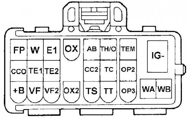
Pin designations on the DLC diagnostic board
You can determine whether there are any malfunctions in the operation of the internal combustion engine (ICE) and gearbox by two symptoms:
- the LED bulbs blinked evenly with a single interval and duration of 11 times;
- The Check indicator blinks long and evenly with intervals of 4.5 seconds.
If there is no contact diagram on the cover or it has been erased, you can determine the required pins as follows:
- The ignition system in the car is turned on.
- One of the contact elements of the light indicator is connected to any standard engine “ground” bolt.
- The second output of the light bulb is connected in turn to each contact of the diagnostic block.
- When the Check indicator lights up on the instrument panel, you can conclude that the desired pin has been found.
To read the code, you need to count the number of LED blinks:
- when a combination appears, the LED blinks quickly, flashes for a few tenths of a second;
- the time interval between decimal and unit readings will be no more than 1.5 s;
- the pause between each subsequent code will be 2.5 seconds;
- Series of codes for different malfunctions are separated by a pause of 4.5 seconds.
How to reset the error?
To clear the fault code, perform the following steps:
- The ignition system in the car is turned on.
- On the diagnostic board, to reset the control unit memory, the TC and E1 contacts are closed.
- Within the next three seconds, the user must press the brake pedal at least 8 times.
- Then you need to make sure that the LED indicator blinks with a pause of 0.5 seconds.
- The ignition is turned off and the jumper is disconnected from the pins. If the error codes are successfully reset, the anti-lock brake system indicator does not light up on the instrument panel.
GOOD TO KNOW
You can use a computer to clear fault codes. If the diagnosis was performed using a laptop, software is used to reset the memory.